


DIN Rail Universal Dimmer Crestron DIN-1DIMU4
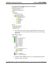
NOTE: Certain third party DIN cabinets provide space for an
informational label between each DIN rail row. Crestron’s Engraver
software (version 4.0 or later) can generate appropriate labels for all
Crestron DIN rail products.
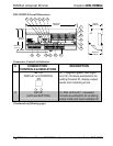
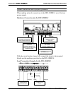
Hardware Hookup
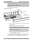
Make the necessary connections as called out in the illustration that
follows this paragraph. Refer to “
Network Wiring” on page 13 before
attaching the 4-position terminal block connector. Apply power after all
connections have been made.
WARNING: Prior to connecting the device, turn off power at the circuit
breaker. Failure to do so may result in serious personal injury or damage
to the device. Restore power after all connections have been made.
CAUTION: Connecting this device to the wrong type of load or
short-circuiting the load can cause severe product damage. Each load
should be tested to identify a short circuit condition prior to wiring the
load to the module.
NOTE: Install in accordance with all local and national electric codes.
NOTE: High-voltage connections accept 2.5 mm
2
(12 AWG) wire. Wire
should be stripped to 8 mm (1/3 inch). Tighten terminal blocks to 0.5 Nm
(5 in-lbs).
NOTE: Use copper wire only. For high-voltage connections, use wire
rated for at least 75º C (167º F).
NOTE: The DIN-1DIMU4 power feed must be protected by a 10 A (trip
curve C) breaker or equivalent.
NOTE: The DIN-1DIMU4 outputs must be used for control of
permanently installed lighting loads only.
NOTE: Do not mix magnetic and electronic transformers on the same
dimmer output.
16 • DIN Rail Universal Dimmer: DIN-1DIMU4 Operations & Installation Guide – DOC. 6668A