


13
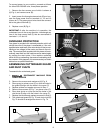
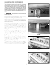
CHECKING, ADJUSTING AND
REPLACING KNIVES
1. When checking, adjusting or replacing the cutter-
head knives on the planer, proceed as follows:
A. DISCONNECT MACHINE FROM
POWER SOURCE
B. Remove the top cover of the planer exposing the
cutterhead.
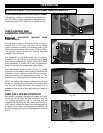
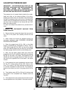
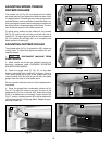
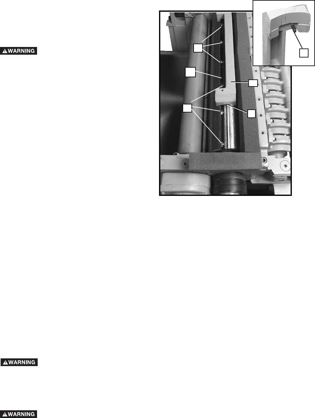
C. Check all four knives for proper setting using the
knife guage (A), as shown in Fig. 20. When the
guage (A) is placed on the cutterhead and the bot-
tom of the two roll pins, one of which is shown at (B),
are against the edge of the slot (C) opposite the
knife, the knife should just contact the bottom of the
guage (D).
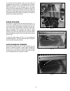
D. If any of the knives require an adjustment, slightly
loosen the knife locking bar of each of the four
knives by turning the knife locking screws (E) Fig.
20, into the locking bar just enough to relieve stress
in the cutterhead but not disturb the setting of the
four knives.
E. To adjust the knife that must be reset, loosen all of
that knife's locking screws (E) Fig. 20, by turning
them into the locking bar. As the knife locking bar
becomes loose, lifter springs under the knife will
raise the knife until it contacts the bottom of the
guage (D). Then snug up the knife locking bar by
lightly backing out the locking screws (E) against the
knife slot. IMPORTANT: AT THIS TIME, ONLY
TIGHTEN THE KNIFE INTO THE SLOT ENOUGH TO
HOLD IT IN POSITION.
F. If additional knives must be reset, repeat STEP C.
G. After all four knives are set with the screws just
snug, back out and tighten the locking screws, five
of which are shown at (E) Fig. 20, against the slot.
Start with the end screws first and proceed on alter-
nate sides toward the center screws until the knife is
securely held in the cutterhead. Tighten the remain-
ing three knives in the same manner.
2. IF THE KNIVES ARE TO BE
REMOVED FOR SHARPENING OR REPLACEMENT,
EXTREME CARE SHOULD BE TAKEN AS THE
KNIVES ARE VERY SHARP. TO REMOVE THE
KNIVES, WEAR GLOVES AND PROCEED AS FOL-
LOWS:
A. DISCONNECT MACHINE FROM
POWER SOURCE
Fig. 20
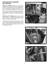
B. To remove each knife, loosen the knife locking bar,
by turning the locking screws, five of which are
shown at (E) Fig. 20, into the knife locking bar and
remove the locking bar, knife and springs located
under the knife.
C. Remove the remaining three knives in the same
manner.
D. Thoroughly clean the knife slots, knife bars, springs
and screws. If the threads appear worn or stripped
or if the heads are becoming rounded, replace them.
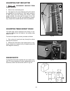
E. Inspect the cutting edge of the knives for nicks or
wire edge. Hone the knives slightly using a stone or
if the knives are to be sharpened, maintain a cutting
angle of 40 degrees.
F. Insert springs, knives and knife locking bars into all
four slots in the cutterhead. Push knives down as far
as possible and back out locking screws, five of
which are shown at (E) Fig. 20, just enough to hold
all four knives in the cutterhead.
G. Adjust all four knives as explained in Step 1.
B
A
D
E
E
C