


20
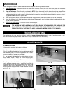
When using your machine, follow these few simple steps for achieving the best results.
1. T
rue Up One Face – Feed one face of the board over a jointer, making thin cuts with each pass, until the entire
surface is flat.
2. Plane
to Thickness – Place the side you planed in STEP 1 face down and feed the board through the planer. Plane
until this side is flat, then plane both sides of the board until you are satisfied with the thickness. Make thin cuts,
and alternate sides with each pass. If, during the planing operation, you notice the board twisting, warping, or bow-
ing, repeat STEP 1 and true up one face.
3. When planing long stock, provide table extensions to support the infeed and outfeed end of the workpiece.
4. Plane with the grain only, and keep planer table clean. Occasionally, wax the table surface to reduce friction dur-
ing the planing operation.
5. Cr
oss-cut to Final Length – Cross-cut lumber to final length.
THE KNIVES ON THE PLANER WILL NOT WEAR EVENLY IF THE WOOD IS FED THROUGH THE
SAME SPOT ON THE TABLE EVERY TIME. FEED THE WOOD THROUGH THE PLANER AT DIF-
FERENT SPOTS ON THE TABLE TO HELP ELIMINATE UNEVEN WEAR OF THE KNIVES.
MACHINE USE
TROUBLESHOOTING
For assistance with your machine, visit our website at www
.deltamachinery.com
for a list of service centers or call
the DELTA Machinery help line at 1-800-223-7278 (In Canada call 1-800-463-3582).
MAINTENANCE
LUBRICATION
Your machine requires lubrication as follows:
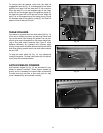
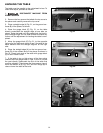
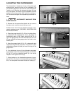
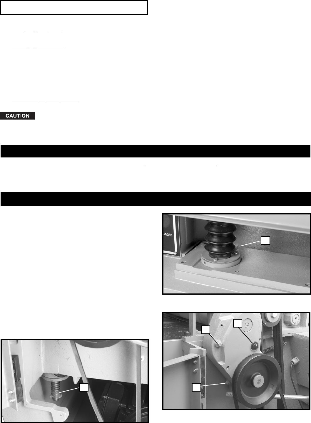
1. The four grease fittings, one of which is shown at (A)
Fig. 41, located at the base of the four table posts are to
be lubricated every 100 hours of operation with an auto-
motive type lithium grease or equivalent.
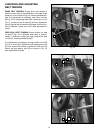
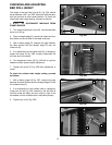
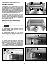
2. As required, lubricate the four table raising and low-
ering screws, three of which are shown at (B) Fig. 42,
with an automotive type lithium grease or equivalent.
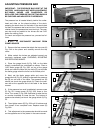
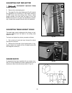
3. The gear box oil should be changed once a year
using extreme pressure gear oil, available from Delta in
one pint cans under part number 999-01-013-1210. The
gear box drain plug is shown at (C) Fig. 43. The oil fill
screw is shown at (B) and the oil level indicator is shown
at (A) Fig. 43.
Fig. 41
Fig. 43
Fig. 42
A
B
B
A
C