


9
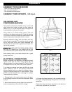
To connect power to your machine, proceed as follows
for either 200-230/460 volts, three phase operation.
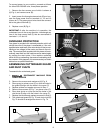
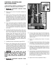
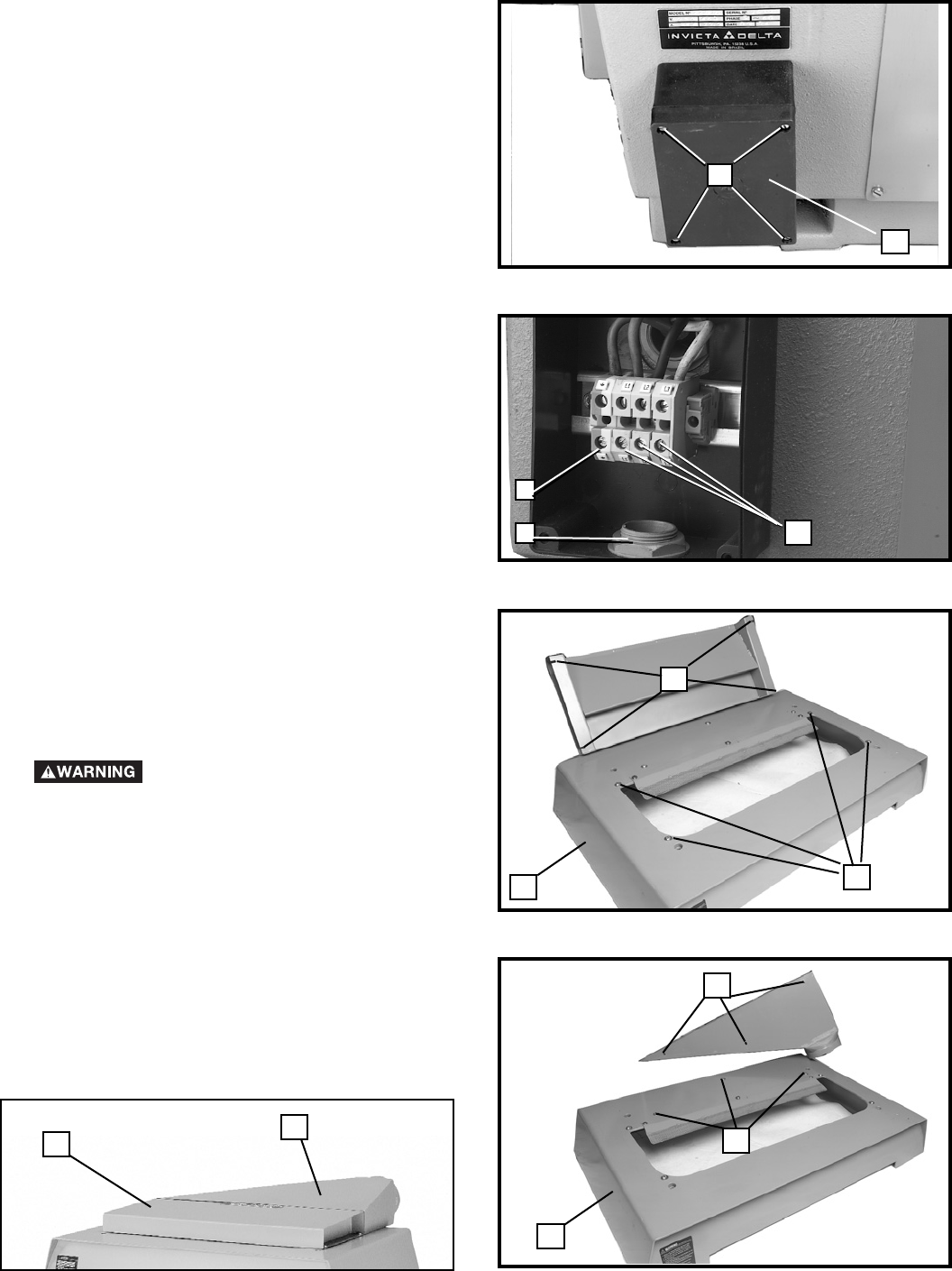
1. Remove the four screws, one of which is shown at
(A) Fig. 4, and remove cover (B).
2. Insert power line through entrance hole (E) and con-
nect the three power lines to terminals L1, L2 and L3
(shown at C). The green ground wire should be connect-
ed to the ground terminal (J).
3. Replace cover (B) Fig. 4.
IMPORTANT: If after the machine is in operation, the
cutterhead turns in the wrong direction, interchange any
two of the three power lines (C) that are connected to
terminals L1, L2 and L3.
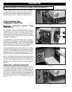
OVERLOAD PROTECTION
Your planer is provided with overload protection which will
shutoff the motor if the planer is overloaded or if line volt-
age falls below safe levels, lithe motor shuts off due to over-
loading or low voltage, let the motor cool three to five min-
utes. The overload block supplied with this planer will auto-
matically reset itself and the machine can be started again
by pushing the start button. If the machine continually
shuts off due to overloading, the cause of overloading must
be corrected. If this happens, it is recommended you obtain
advice from a qualified electrician.
Fig. 4
Fig. 5
Fig. 6
Fig. 7
ASSEMBLING CUTTERHEAD GUARD
AND DUST CHUTE
To assemble the cutterhead guard:
1. DISCONNECT MACHINE FROM
POWER SOURCE
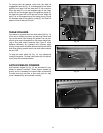
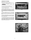
2. Remove four screws and washers at (A) Fig. 6.
3. Place guard on planer cover (C) so that the holes in
the guard (B) align with the holes in the cover (C).
4. Replace screws and washer removed in Step 1.
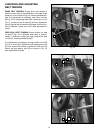
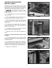
5. Remove three screws (E) Fig. 7 on planer cover (C).
6. Place dust chute on cover so that the holes in the
dust chute (D) align with the holes in the cover (C).
7. Replace the screws and washers removed in Step 5.
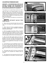
8. The cutterhead guard (B) Fig. 7A and dust chute (D)
Fig. 7A should be arranged as shown in Fig. 7A
A
E
C
J
B
A
B
C
E
C
D
Fig. 7A
D
B