


17
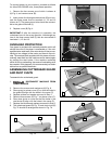
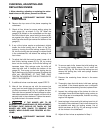
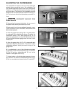
ADJUSTING THE CHIPBREAKER
The chipbreaker is located on the top of the planer and
extends down around the front of the cutterhead. The
chip-breaker segments raise as stock is fed through and
"break or curl" the chips the same as the plane iron cap
on a hand plane. The bottom of the chipbreaker must be
parallel to the knives and set .040" below the cutting cir-
cle. To check and adjust the chipbreaker, proceed as fol-
lows:
1. DISCONNECT MACHINE FROM
POWER SOURCE
2. Remove the four screws that attach the top cover to
the planer and carefully remove the top cover.
3 Make certain the knives are adjusted properly as pre-
viously explained under CHECKING, ADJUSTING AND
REPLACING KNIVES.
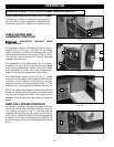
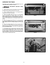
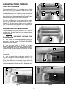
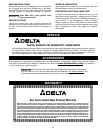
4. Place the guage block (A) Fig. 29, on the table direct-
ly underneath the cutterhead as shown. To adjust the
chipbreaker, place a .040" feeler gauge (B) Fig. 29, on
top of the guage block and raise the table until the knife
(C) just touches the feeler guage when the knife is at its
lowest point.
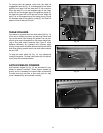
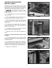
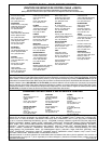
5. Move the guage block (A) Fig. 30, underneath each
chipbreaker segment (B) as shown. The bottom of each
chipbreaker segment should just touch the top of the
guage block.
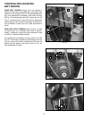
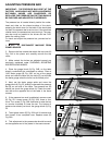
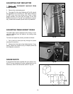
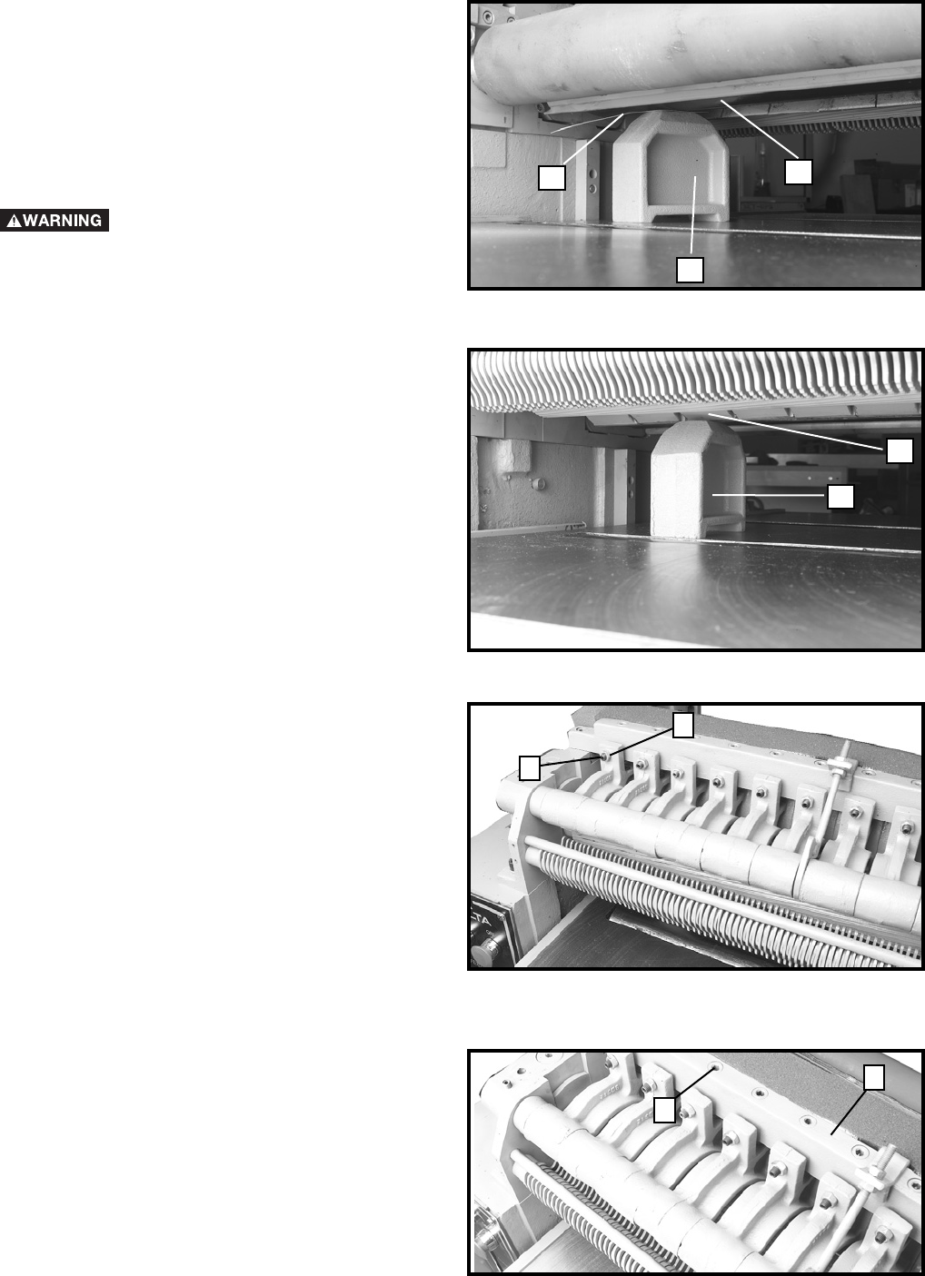
6. If an adjustment to any of the chipbreaker segments
is necessary, loosen the corresponding lock nut, such as
(C) Fig. 31, and turn adjusting screw (D) in or out as
required. Then tighten lock nut (C).
7. Spring tension on the chipbreaker segments is prop-
erly set when the head of corresponding screw (E) Fig.
32, is two complete turns below surface of casting (F).
Fig. 29
Fig. 30
A
B
A
C
B
Fig. 31
Fig. 32
D
C
F
E