


19
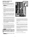
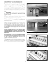
Fig. 38
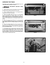
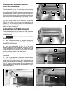
Fig. 39
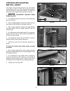
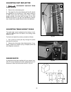
Fig. 40
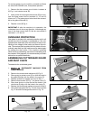
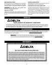
ADJUSTING CHIP DEFLECTOR
1. DISCONNECT MACHINE FROM
POWER SOURCE
2. Remove the cutterhead guard.
3. The edge (C) of the chip deflector (A) Fig. 38, should
be adjusted so it is a minimum of .040" and a maximum
of .080" away from the cutting circle. Place a feeler
gauge between the knife and the edge of the chip
deflector as shown in Fig. 38. If an adjustment is neces-
sary, loosen three screws (B) and move chip deflector.
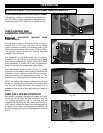
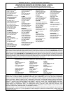
ADJUSTING TABLE HEIGHT SCALE
The table height scale is adjusted at the factory to indi-
cate the distance from the table to the cutting circle
(depth of cut).
To check and adjust the pointer, proceed as follows:
1. Run a piece of wood part way through the planer
and stop the machine.
2. Measure the thickness of the finished piece. If nec-
essary, loosen two screws (A) Fig. 39 adjust pointer (B)
and retighten screws (A).
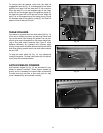
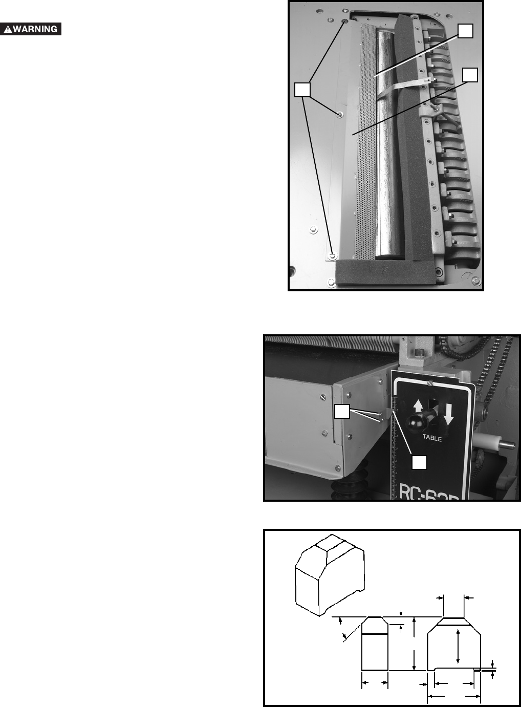
GAUGE BLOCK
A gauge block has been supplied with your planer; how-
ever, if it is ever necessary to make a gauge block out of
hardwood, follow the instructions shown in Fig. 40.
4"
1
/4"
45°
2"
3"
4"
1
1
/2"
1
/2"
GRAIN
C
A
B
A
B