


16
Fig. 24B
Fig. 25
Fig. 26
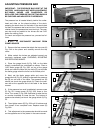
ADJUSTING PRESSURE BAR
IMPORTANT: THE PRESSURE BAR IS SET AT THE
FACTORY AND SHOULD NOT NEED ASJUSTMENT.
BUT WHEN KNIVES ARE SHARPENED OR
REPLACED THE PRESSURE BAR SETTING SHOULD
BE CHECKED AND ADJUSTED IF NECESSARY.
The pressure bar is located directly behind the cutter-
head and rides on the planed surface of the stock,
pressing the stock down on the table. If the stock does
not feed, the pressure bar is set too low. If the stock has
chatter marks, the pressure bar is set too high. The pres-
sure bar must be parallel to the knives and set .040"
below the cutting circle.
To check and adjust the pressure bar, proceed as fol-
lows:
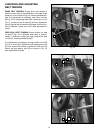
1. DISCONNECT MACHINE FROM
POWER SOURCE
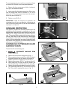
2. Remove the four screws that attach the top cover (A)
Fig. 24A to the planer and carefully remove the top
cover.
3. Make certain the knives are adjusted properly as
previously explained under CHECKING, ADJUSTING
AND REPLACING KNIVES.
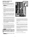
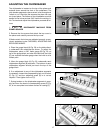
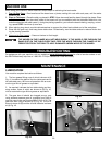
4. Place the guage block (A) Fig. 24B, on the table
directly underneath the cutterhead as shown. Place a
.040" feeler guage (B) Fig. 24B, on top of the guage
block and raise the table until the knife (C) just touches
the feeler guage when the knife is at its lowest point.
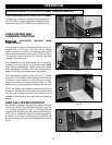
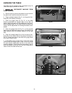
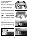
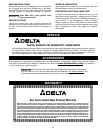
5. Next, set the feeler guage aside and move the
guage block (A) Fig. 25, directly underneath the pressure
bar (B) on one end of the table. The pressure bar (B)
should just touch the guage block (A). Check the pres-
sure bar at the opposite end of the table in the same
manner.
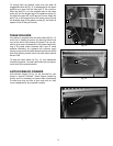
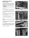
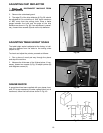
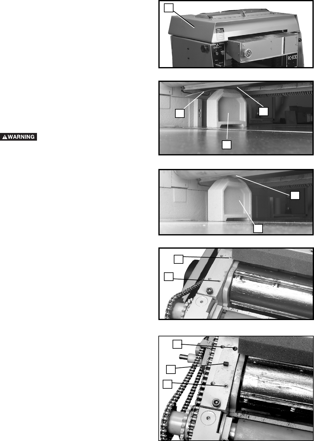
6. If the pressure bar must be adjusted, remove screw
(D) Fig. 26. Loosen screw (E) Fig. 26A, three or four
turns. Turn screw (F) Fig. 26A clockwise to raise the bar
or counter clockwise to lower the bar. The bottom of
pressure bar should just touch the gauge block (A) Fig.
25.
8. Then tighten screw (E) Fig. 26A until it bottoms and
then loosen it two complete turns. Replace screw (D)
Fig. 26A.
9. This adjustment to the pressure bar should be made
on the opposite end of the planer In the same manner.
B
A
C
A
B
D
Fig. 24A
A
Fig. 26A
E
D
F
E