


13
Fig. 32
Fig. 33
Fig. 34
Fig. 35
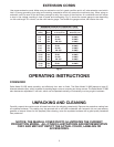
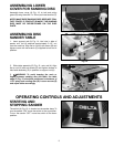
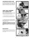
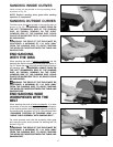
ACCESSORY MITER GAGE
An accessory miter gage is available for your machine
and is used with the disc table. The miter gage body (A)
Fig. 32, can be tilted right or left for angle or miter
sanding by loosening lock knob (B), and rotating miter
gage body to the desired angle. Tighten lock knob (B).
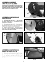
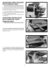
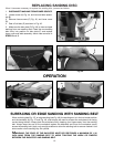
DUST SPOUT
A dust spout (A) Fig. 35, is supplied with your sander and
can easily be connected to a standard shop vacuum
hose. The inside diameter opening of the dust spout (A)
is 2-1/4 inches.
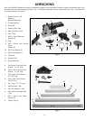
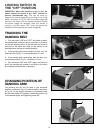
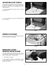
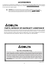
USING TABLE ASSEMBLY
WITH SANDING BELT
When the sanding arm (A) Fig. 33, is in the vertical
position, the complete table assembly (B) can be moved
from the disc unit to the belt unit as follows:
1. Remove backstop (C) Fig. 33, from the machine.
2. Loosen screw (D) Fig. 33, and carefully remove sup-
port bar (E) and table assembly (B) from the disc unit.
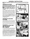
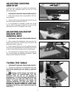
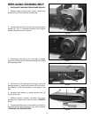
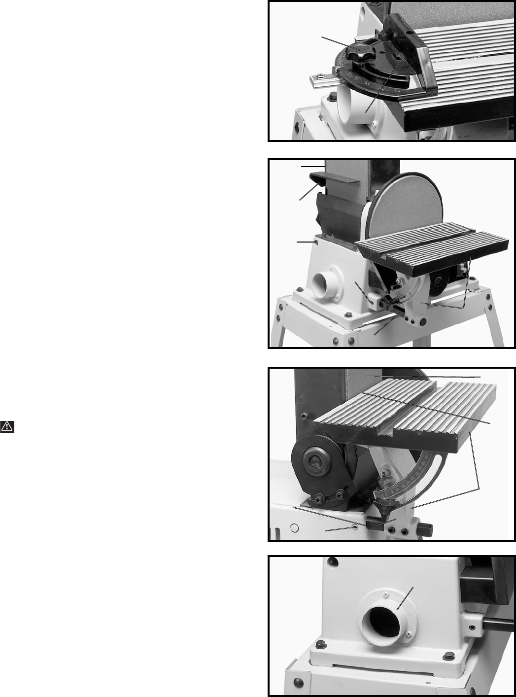
3. Loosen set screw (F) Fig. 34, and insert support bar
(E) and table assembly (B) into hole (G) Figs. 33 & 34, on
belt unit. Tighten set screw (F) to hold support bar and
table assembly in position.
WARNING: THE TABLE EDGE (H) FIG. 34, MUST
BE POSITIONED A MAXIMUM OF 1/16" AWAY FROM
SANDING BELT (J) TO AVOID TRAPPING THE WORK
OR FINGERS BETWEEN THE TABLE AND SANDING
BELT.
A
B
A
C
B
D
E
B
F
G
E
H
J
A
G