


6
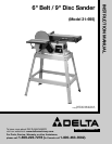
UNPACKING
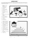
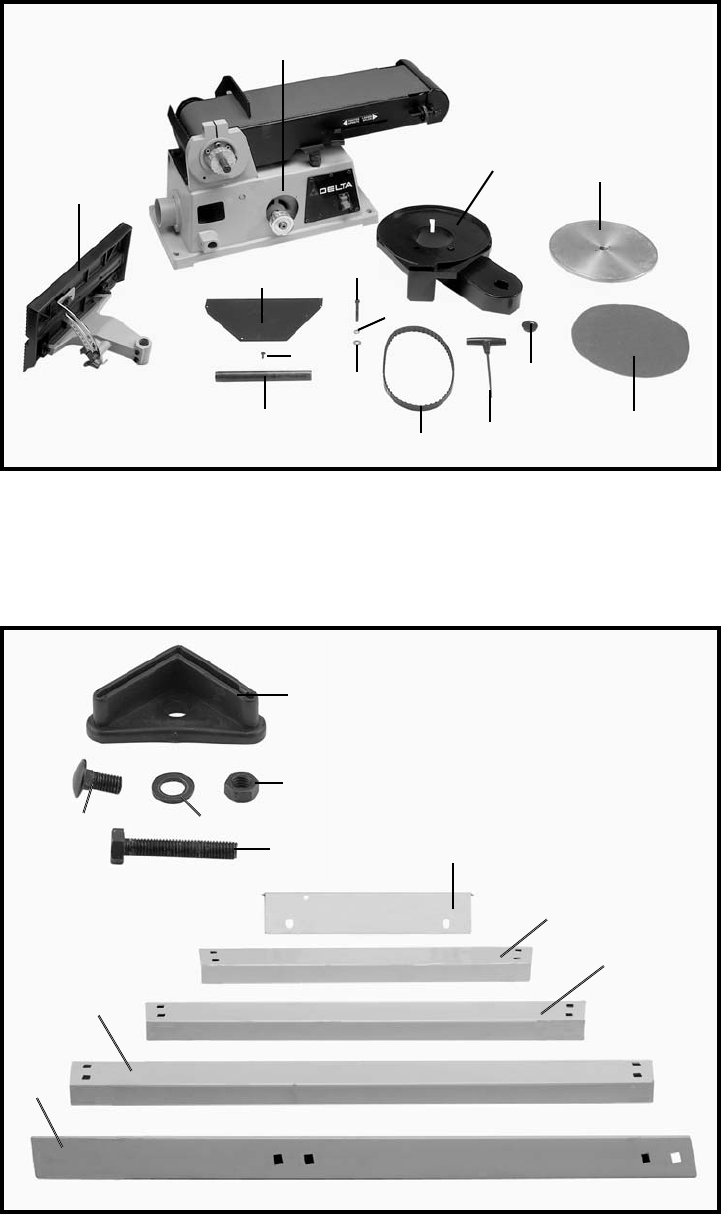
Your new Belt/Disc Sander and Stand is shipped complete in one container. Carefully unpack the sander, stand, and
all loose items from the shipping container. Fig. 2, illustrates the sander and its component parts. Fig. 3, illustrates the
component parts of the stand.
A Two Upper Front and Rear
Braces - 11-1/2" long
B Two Lower Front and Rear
Braces - 17-1/8" long
C Two Upper Side Braces -
21-5/16" long
D Two Lower Side Braces -
26-5/8" long
E Four Legs - 27-1/2" long
F M8 Hex Nuts - (36)
G 3/8" Flat Washers - (40)
H M8 x 20mm Carriage Bolts
- (32)
J M8 x 45mm Hex Head
Screws (4)
K Plastic Feet (4)
Fig. 2
Fig. 3
1. Sander with 6" x 48"
Sanding
Belt and Backstop
2. 9" Sanding Disc
3. Drive Belt
4. Sanding Disc Plate
5. Belt and Pulley Cover
6. Disc Cover
7. M4.2 x 13mm Panhead
Screws (3)
8. Plug
9. M6 x 55mm Hex Socket
Head
Screws (2)
10. M6.4 Flat Washer (2)
11. M6.4 Lockwasher (2)
12. T-Wrench
13. Support Rod
14. Table Assembly
1
2
3
4
5
6
7
8
9
10
11
12
13
14
E
A
B
C
D
F
G
H
J
K