


9
Fig. 13
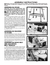
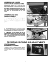
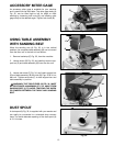
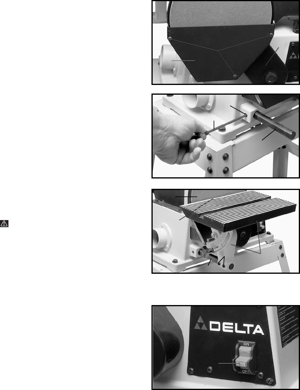
ASSEMBLING LOWER
COVER FOR SANDING DISC
Assemble lower cover (A) Fig. 13, to belt and pulley
guard (B) using three M4.2 x 13mm pan head screws (C).
NOTE: MAKE SURE SANDING DISC DOES NOT CON-
TACT COVER. IF CONTACT IS MADE, THE SANDING
DISC MUST BE REPOSITIONED ON THE DISC
PLATE.
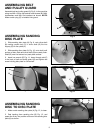
Fig. 14
Fig. 15
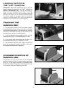
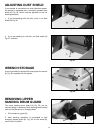
ASSEMBLING DISC
SANDER TABLE
1. Insert support rod (A) Fig. 14, into hole in side of
sander until rod (A) extends approximately 5-1/2" out
from the machine. Align flat on rod (A) with screw (B) and
tighten screw with hex wrench (C) supplied to hold rod in
position.
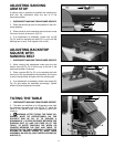
2. Slide table assembly (D) Fig. 15, onto rod (A). Align
flat on rod (A) with set screws (E) and tighten screws to
hold table assembly (D) in position on support rod (A).
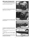
3. WARNING: To avoid trapping the work or
fingers between sanding disc and table, the table
edge (F) Fig. 15, should be positioned a maximum of
1/16" away from sanding disc (G). Loosen screws (E)
and adjust table accordingly.
C
B
A
C
B
A
G
A
E
F
D
OPERATING CONTROLS AND ADJUSTMENTS
Fig. 19
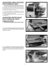
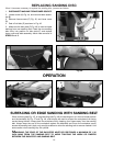
STARTING AND
STOPPING SANDER
The switch (A) Fig. 19, is located on the sander base. To
turn the sander “ON” move the switch to the up position.
To turn the sander “OFF” move the switch to the down
position.
A