


15
Fig. 40
Fig. 41
Fig. 42
Fig. 43
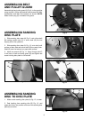
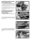
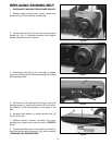
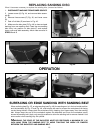
5. Slide new 6" x 48" sanding belt (F) Fig. 43, over both
sanding drums (G), making sure the belt (F) will travel in
the direction of the arrow located on the inside of the
belt.
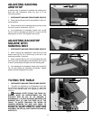
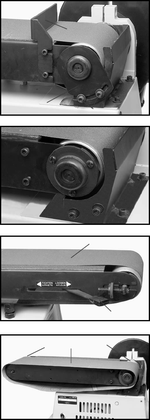
6. Re-apply belt tension by sliding tension lever (E)
Fig. 42, to the left.
7. Replace support bracket, backstop and upper
sanding drum guard which were removed in STEPS 2
and 3.
8. Connect electrical power to the sander and check to
see if the belt is tracking properly. If not, refer to section
“TRACKING THE SANDING BELT.”
4. Slide tension lever (E) Fig. 42, to the right to release
tension on sanding belt (F). Remove sanding belt (F) from
both sanding drums.
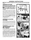
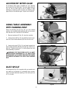
REPLACING SANDING BELT
1. DISCONNECT MACHINE FROM POWER SOURCE.
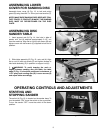
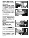
2. Remove upper sanding drum guard. Loosen two
screws (A) Fig. 40, and remove backstop (B).
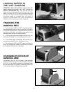
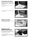
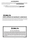
3. Loosen two screws (C) Fig. 40, and remove support
bracket (D). Fig. 41 illustrates backstop and support
bracket removed from the machine.
C
D
B
A
E
F
G
F
G