


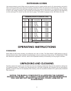
7
ASSEMBLY INSTRUCTIONS
WARNING: FOR YOUR OWN SAFETY, DO NOT CONNECT THE SANDER TO THE POWER SOURCE UNTIL
THE MACHINE IS COMPLETELY ASSEMBLED AND YOU READ AND UNDERSTAND THE ENTIRE OWNERS
MANUAL.
ASSEMBLING STAND
IMPORTANT: ANY LETTER DESIGNATIONS THAT
MAY BE STAMPED ON THE BRACES OF THE STAND
ARE FOR PRODUCTION PURPOSES ONLY AND ARE
NOT USED FOR ASSEMBLING THE STAND. TO
ASSEMBLE THE STAND, PLEASE FOLLOW THE
INSTRUCTIONS DESCRIBED BELOW. SIZES ARE
GIVEN TO HELP IDENTIFY THE COMPONENTS OF
THE STAND.
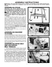
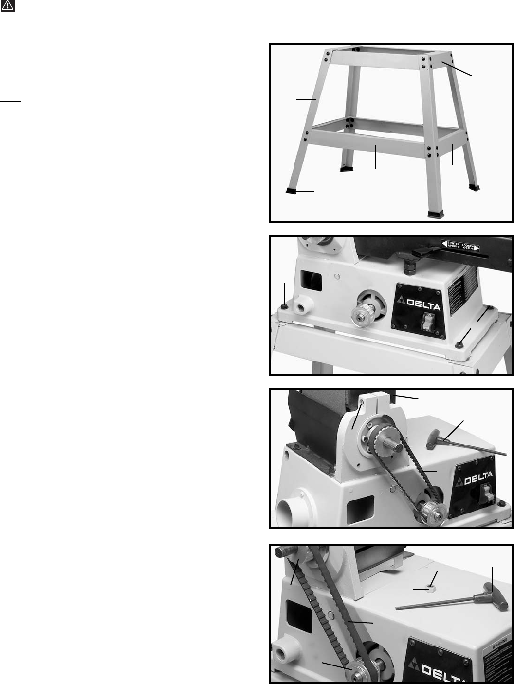
1. Assemble the stand, as shown in Fig. 4. Align the
holes in the stand and fasten the stand together by
inserting a M8X20mm carriage head bolt through the
hole and place a 3/8" flat washer onto the carriage head
bolt and thread a M8 hex nut onto the screw and tighten
securely, repeat this process for the thirty one remaining
holes. The two 11-1/2" long upper braces (A); 21-5/16"
long upper braces (B); 17-1/8" long lower braces (C); and
26-5/8" long lower braces (D) should be fastened to the
four 27-1/2" long legs (E). IMPORTANT: The top angles
of the upper braces (A) should be on top of the top
angles of upper braces (B).
2. Assemble a plastic foot (F) Fig. 4, to the bottom of
each leg (E) as shown.
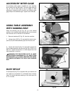
ASSEMBLING MACHINE
TO STAND
Carefully set the sander on the stand. Align the four holes
on the top of stand (A) Fig. 5, with four mounting holes at
the base of sander (B). Place a 3/8" flat washer onto a
M8 x 45mm hex head screw (C), insert screw through
hole in base of sander (B) and stand (A). Place a 3/8" flat
washer onto the screw and thread a M8 hex nut onto the
screw and tighten securely, repeat this process for the
three remaining holes.
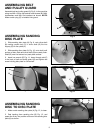
ASSEMBLING DRIVE BELT
AND ADJUSTING
BELT TENSION
1. With hex wrench (A) Fig. 6 supplied, loosen screw (B)
and move sanding arm (C) to the vertical position; tighten
screw (B) as shown. Assemble drive belt (D) to pulleys.
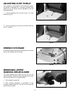
2. NOTE: The drive belt (D) Fig. 7, should be firm but
not too tight on the pulleys, the drive belt (D) should
have approximately 1/4" to 1/2" deflection in the belt
at the center span on the pulleys (E) and (F) using
light finger pressure. The drive belt (D) does not
require excessive tension to function properly. To
adjust belt tension, loosen locknut (G) Fig. 7. Using
wrench (A) tighten or loosen adjustment screw (H) until
correct belt tension is obtained. Then tighten locknut (G).
3. After drive belt (D) Fig. 7, is tensioned properly, move
the sanding arm to the horizontal position.
Fig. 4
Fig. 5
Fig. 6
Fig. 7
A
B
C
D
E
F
A
B
C
C
B
C
A
D
E
D
F
H
G
A