


14
OPERATION
Fig. 33
Fig. 34
Fig. 35
Fig. 37Fig. 36
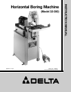
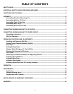
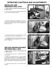
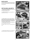
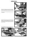
Figs. 33 and 34, illustrate a typical end boring operation.
Note that work holddown (A) Fig. 33, has been adjusted
to hold workpiece (B) down on the table and that the end
of
workpiece (B) is firmly held against table fence (C) and
miter gage (D).
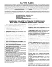
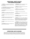
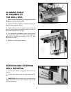
Figs. 35 and 36, illustrate a typical two hole side boring
operation. Note that work holddown (A) Fig. 35, has been
adjusted to hold workpiece (E) down on the table and
that workpiece (E) is firmly held against the table fence
and stock stop (F).
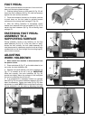
Fig. 37, illustrates the end piece (B) with dowel rods (G)
inserted, about to be assembled to workpiece (E).
A
C
B
D
A
E
F
B
E
G