


9
INSTALLING AND
REMOVING DRILL BITS
1. Make certain the machine is disconnected from
the power source.
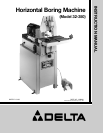
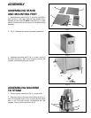
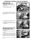
2. Remove four screws, two of which are shown at (A)
Fig. 14, and remove safety shield (B).
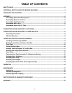
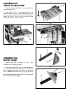
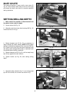
3. Carefully thread drill bit adapters (C) Fig. 15,
supplied, into spindles (D) and tighten drill bit adapters
(C) in position using wrenches on flats of adapters and
spindles as shown.
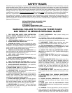
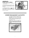
4. Insert drill bit (E) Fig. 16, not supplied, into adapter
(C) and tighten set screw (F) with allen wrench.
5. Install drill bit to the other drill bit adapter in the same
manner. NOTE: Drill bits are available in 1/4”, 5/16”, 3/8”
and 1/2” diameters.
OPERATING CONTROLS AND ADJUSTMENTS
Fig. 14
Fig. 15
Fig. 16
Fig. 17
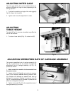
SETTING CENTER DISTANCE
BETWEEN DRILL BITS
1. Make certain the machine is disconnected from
the power source.
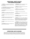
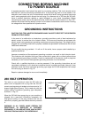
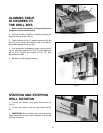
2. With allen wrench (A) Fig. 17, supplied, loosen two
set screws (B).
3. Rotate two cylinders (C) Fig. 17, to the desired
center distance between drill bits (D). NOTE: There are
witness lines on the face of the boring head (E) to
indicate the desired distance between drill bits. NOTE:
Center drilling capacity of supplied boring head is 3/4” to
3”.
4. Tighten set screws (B) Fig. 17, after setting center
distance.
A
B
D
C
C
D
E
F
C
C
A
B
A
D