


15
MAINTENANCE
Fig. 41
Fig. 38
Fig. 39
Fig. 40
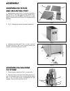
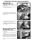
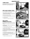
LUBRICATION
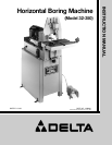
The boring head assembly (A) Fig. 38, should be lubri-
cated periodically with spindle grease Delta Part No.
999-02-023-1441 through the grease fitting (B).
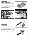
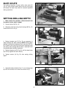
REPLACING BORING HEAD
If it is ever necessary to remove the boring head for
repair or replacement, proceed as follows:
1. Make certain the machine is disconnected from
the power source and air supply.
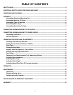
2. Remove four screws, two of which are shown at (A)
Fig. 39, and remove safety shield (B).
3. Loosen screw (C) Fig. 39, and slide boring head (D)
from carriage assembly.
4. Reassemble boring head in the same manner.
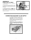
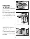
REPLACING
SPINDLE COUPLING
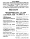
If it is ever necessary to remove the spindle coupling (A)
Fig. 40, for repair or replacement due to wear, proceed
as follows:
1. Make certain the machine is disconnected from
the power source.
2. Remove safety shield and boring head.
3. Thread spindle coupling removal tool (B) Fig. 40,
(supplied) onto spindle coupling (A).
4. Insert allen wrench into socket head screw (C) Fig.
40, located on the head of tool (B) as shown, and turn
allen wrench clockwise until spindle coupling (A) releases
from spindle shaft.
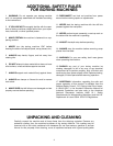
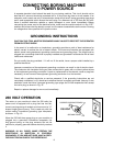
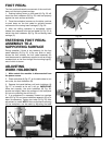
5. To replace spindle coupling (A) Fig. 41, align spindle
coupling with flats on tapered spindle shaft (D).
6. Using a block of wood and mallet, lightly tap on head
of spindle coupling (A) Fig. 41, until it seats firmly on
tapered spindle shaft (D).
7. Replace boring head and safety shield.
A
B
D
B
A
C
C
A
B
D
A