


5
ASSEMBLY
Fig. 2
Fig. 3
Fig. 5
Fig. 4
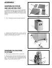
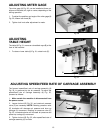
ASSEMBLING STAND
AND MOUNTING FEET
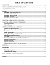
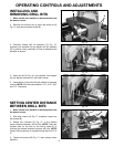
1. Assemble front panel (A) Fig. 2, and rear panel (B) to
side panels (C) with eight 5/8 inch-long screws, lock-
washers and hex nuts (D). NOTE: Holes (E) Fig. 2, in side
panels (C) should be at the bottom of the stand during
assembly.
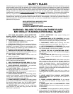
2. Fig. 3, illustrates the stand completely assembled.
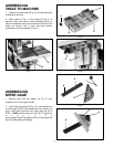
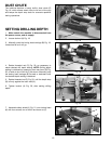
3. Assemble mounting leg (F) Fig. 4, to each corner of
the stand as shown, with 4 one inch-long screws, flat
washers, lockwashers and hex nuts (G).
F
F
F
F
G
ASSEMBLING MACHINE
TO STAND
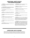
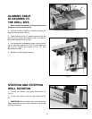
1. Carefully place machine (A) Fig. 5, on stand (B).
2. Align four holes in the base of the machine (A) Fig. 5,
with four threaded holes in top of stand (B) and fasten
with 4 one inch-long screws, lockwashers and flat
washers, three of which are shown at (C).
A
B
D
C
C
E
C
B
A
C