


7
Fig. 11
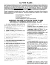
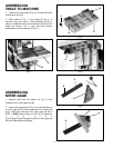
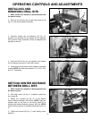
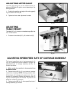
ASSEMBLING
STOCK STOP TO TABLE
1. Loosen two lock knobs (A) Fig. 11, located on the
underside of table (B).
2. With the flat side of stock stop rod (C) Fig. 11, facing
down, slide stop rod (C) through holes at both ends of
table (B) as shown, and fasten by rotating two lock knobs
(A) clockwise.
3. Assemble stock stop (D) Fig. 11, to either
end of the
stop rod (C) and hold in place by rotating lock knob (E)
clockwise. NOTE: Lock knob (E) Fig. 11, must clamp
against flat surface of stop rod (C). Adjustments to stock
stop (D) can be made later.
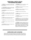
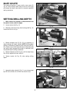
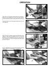
Fig. 12
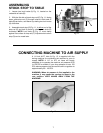
CONNECTING MACHINE TO AIR SUPPLY
A 1/4 inch N.P.T. inlet (A) Fig. 12, is supplied with the
boring machine for connecting the machine to your air
supply. NOTE: A 1/4” to 3/4” air hose will supply
adequate air to operate the machine; air pressure of 60
to 120 PSI is suitable. If your shop pressure is over 120
PSI, reduce pressure into the machine with a regulator to
approximately 90 - 100 PSI.
WARNING: When air pressure is first applied to the
machine, it may cause the carriage to move to the
rear position. KEEP HANDS AWAY FROM THE
MACHINE!
A
D
E
C
A
B
A