


13
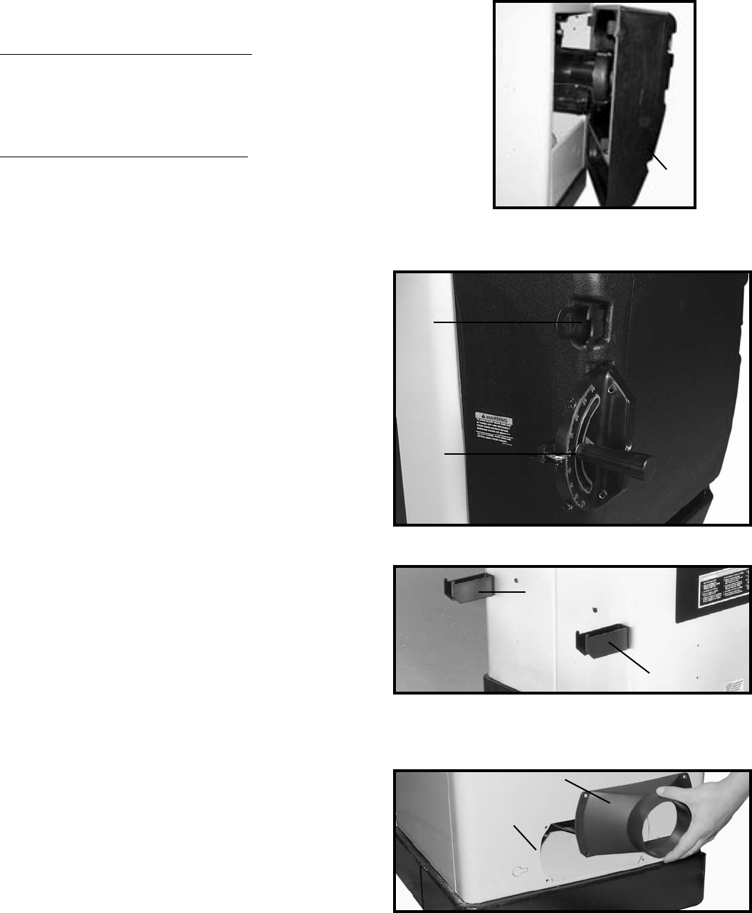
Fig. 31
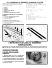
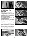
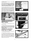
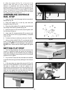
ASSEMBLING RIP FENCE
HOLDER BRACKETS
Assemble the rip fence holder brackets (A) and (B) Fig.
32A, to the four holes located in the left hand side of the
saw cabinet using four #10x1/2" sheet metal screws
supplied.
Fig. 32A
A
B
A
Fig. 32B
A
B
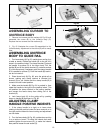
ASSEMBLING DUST CHUTE
ADAPTER
The Unisaw is supplied with a dust chute connector to
provide a means of connecting a 4" diameter dust
collector hose to the machine. Align the four holes in the
dust chute adapter (A) Fig. 32B,with the four holes in the
back of the saw cabinet (B) and attach the dust chute
adapter with four #10 x 1/2" sheet metal screws. NOTE:
DO NOT MOUNT THE DUST CHUTE ADAPTER
UNLESS A DUST COLLECTION SYSTEM IS USED IN
CONJUNCTION WITH THE SAW, FOR THE DUST
CHUTE ADAPTER WILL RESTRICT THE GRAVITY
FEED OPENING FOR SAW DUST REMOVAL.
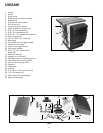
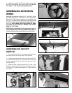
MITER GAGE HOLDER AND
WRENCH HOLDER
The miter gage (A) Fig. 32 and arbor wrenches (B) can be
stored in the slots provided in the motor cover, as shown
in Fig. 32.
Fig. 32
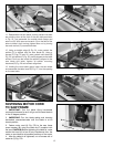
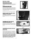
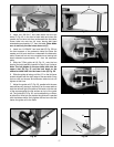
MOTOR COVER
Removing the motor cover
To remove the motor cover, push motor cover to one side
to depress clips, and rotate motor cover away from the
cabinet.
Attaching the motor cover
Place the motor cover (A) in the opening of the Unisaw as
shown in Fig. 31. Place the rear motor cover clips inside
the motor opening and push the front of the motor cover
until all 4 motor cover clips are engaged with the motor
cover opening in the Unisaw.
Fig. 32 shows the motor cover attached to the Unisaw.
A
B