19
ASSEMBLING CURSOR TO
UNIFENCE BODY
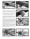
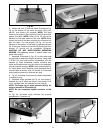
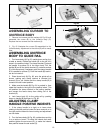
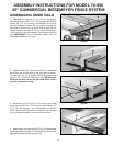
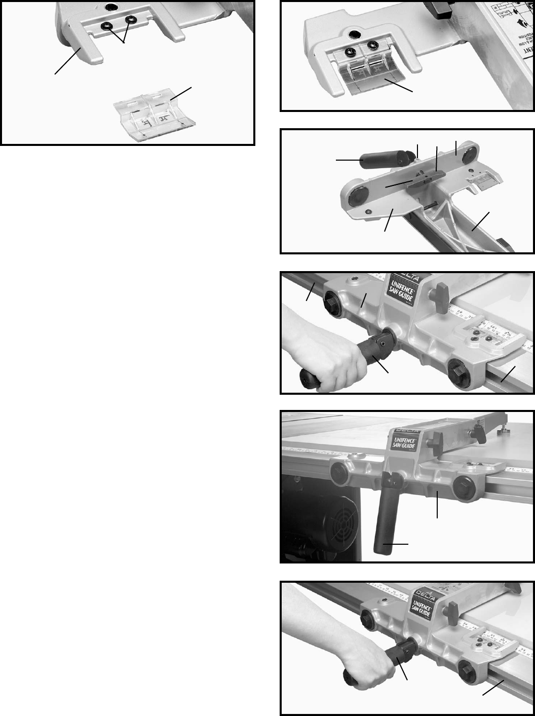
1. Remove two screws and flat washers (A) Fig. 60, and
assemble the cursor (B) to the Unifence body (C).
Replace the two screws and flat washers (A).
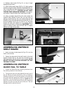
2. Fig. 61 illustrates the cursor (B) assembled to the
Unifence body. Adjustment to the cursor (B) will be made
later.
Fig. 60
Fig. 61
A
C
B
B
Fig. 62
Fig. 63
Fig. 64
B
C
E
F
D
A
B
G
G
B
G
Fig. 65
A
B
ASSEMBLING UNIFENCE
BODY TO GUIDE RAIL
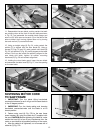
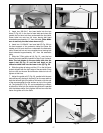
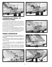
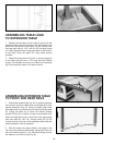
1. Turn fence body (A) Fig. 62, upside down and lay it on
a table or bench. Rotate the handle (B) to the left till it
stops in the positive indent. The clamp bracket (C) should
be parallel to surface (D) of the fence body. Pull the
handle (B) out till the clamp bracket (C) contacts surface
(F) of the fence body. If necessary pivot the clamp bracket
till it is parallel to surface (F). Push the handle (B) back in,
but do not rotate it.
2. Place fence body (A) Fig. 63, onto the guide rail as
shown, making sure clamp bracket is inserted into
channel (G) on rail. Notice that the clamp handle (B) is
turned to the left indent position.
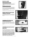
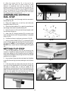
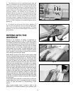
3. Make sure the handle (B) Fig. 64, is pushed in, then
rotate the handle to the right to the positive indent. This
will position the clamp bracket in the locking position,
and prevent the fence clamp from sliding out of the
channel (G).
4. Lock fence body (A) to the guide rail by pushing
down on handle (B) as shown in Fig. 65.
A
ADJUSTING CLAMP
HANDLE POSITIVE INDENTS
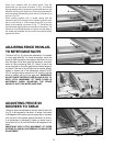
1. If the clamp handle is to tight or to loose when
rotating to the left positive indent for fence removal, or to
the right positive indent for fence locking and adjustment
can be made.
2. Turn the fence body (A) Fig. 62, upside down and lay
it on a table or bench. To make the indents feel more
positive tighten the set screw (G), to make the indents
less positive loosen the set screw (G).
G


