8
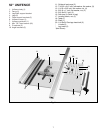
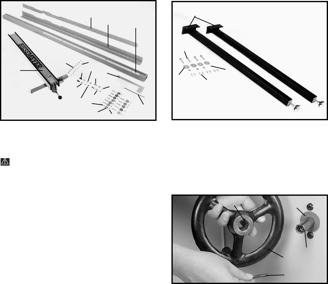
50" COMMERCIAL BIESEMEYER FENCE SYSTEM
NOTE: A common hardware package is used for
several different models, therefore you may have
leftover hardware. Fig. 4
1 - Rear Rail
2 - Front Rail
3 - Guide Tube
4 - T-Square
®
Fence Assembly
5 - Cable Strap
6 - Template for aligning front rail to saw table
for fastening front and rear rails to right extension
table Fig. 4
7 - 1-1/2" long flat head Phillips screws (12)
8 - 1-1/4" O.D. Flat Washers (12)
9 - 1/4-20 hex nuts (12)
for fastening rear rail to saw table Fig. 4
10 - 3/8-24 x 1-1/4" long hex head cap screws (2)
11 - 7/8" O.D. flat washers (2)
12 - Lock washers (2)
for fastening front rail to saw table Fig. 4
13 - 3/8-16 x 1-1/4" long flat head Phillips screws (2)
14 - 7/8" O.D. flat washers (2)
15 - Lock washers (2)
16 - 3/8-16 hex nuts (2)
for fastening guide tube to front rail Fig. 4
17 - 1/2 long hex screws (9)
18 - Lock washers (9)
leg hardware Fig. 5
19 - Legs (2)
20 - 5/8" long wood screws #8 (8)
21 - 1/4-20 x 1-1/2" long flat head phillips screws (4)
22 - 1/4" flat washers (4)
23 - 1/4-20 hex nuts (4)
1
2
3
4
5
6
7
8
9
12
10
11
13
14
15
16
17
18
19
20
21
22
23
LIMITED EDITION UNISAW ASSEMBLY
INSTRUCTIONS
WARNING: FOR YOUR OWN SAFETY, DO NOT CONNECT THE SAW TO THE POWER SOURCE UNTIL THE
SAW IS COMPLETELY ASSEMBLED AND YOU READ AND UNDERSTAND THE ENTIRE INSTRUCTION MANUAL.
Fig. 4
Fig. 5
ASSEMBLING BLADE
TILTING MECHANISM
HANDLE
1. Install fiber washer (A) Fig. 6A, on the blade tilting
mechanism shaft (B). Install key (C), into shaft keyway.
2. Place handwheel (D) on shaft (B) Fig. 6A. Make sure
the groove (E), in the handwheel lines up with the key (C).
3. Push the handwheel snugly against the fiber washer
and tighten the set screw.
Fig. 6A
C
B
A
D
E


