ASSEMBLING UNIFENCE
GUIDE RAIL TO TABLE
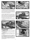
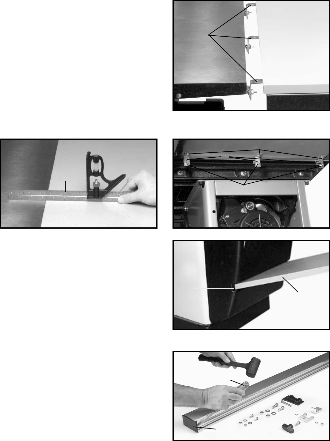
1. Locate the Guide Rail and mounting hardware from
the packing material of the Unifence.
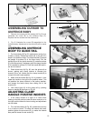
2. The guide rail has end caps inserted into each end of
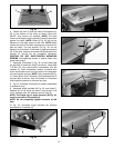
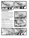
the rail. Remove the end cap (B) Fig. 48, by inserting a
flathead screwdriver (C) into the channel in the guide rail
and press outward against the inside of the end cap (B)
as shown. The end cap (B) will pop out. NOTE: Do not
attempt to remove the end cap by forcing the screwdriver
between the end cap and the end of the rail. This will
damage both the cap and the rail.
Fig. 48
C
B
16
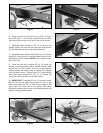
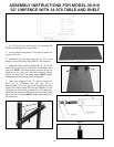
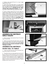
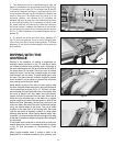
11. Position table board (R) Fig. 45, on top of angle
brackets (N) as shown.
12. While holding table board (R) Fig. 45, tightly against
extension wing (K), fasten table (R) to brackets (N) Fig. 45,
from underneath the table using three #8 x 7/8 inch-long
wood screws (Q) Fig. 47. CAUTION: DO NOT OVER-
TIGHTEN TABLE MOUNTING SCREWS. Over-tighten-
ing screws in particle board may cause them to strip.
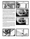
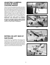
13. Using a straight edge (S) Fig. 46, make certain the
Unifence table surface is level with the saw table by
placing a square (S) Fig. 46 on the table board and the
extension wing, and then adjust the brackets (N) Fig. 45,
and then tighten nuts (P) Fig. 45. Place a 3 ft. long level
across the table and adjust the two leveling screws
located on the bottom of table legs. IMPORTANT: Front
edge of Unifence table must be flush with or slightly
behind front edge of saw table.
Fig. 45
N
R
Fig. 47Fig. 46
Q
P
K
S
N
ASSEMBLING UNIFENCE
SHELF BOARD
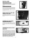
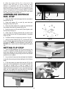
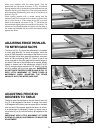
1. Insert one end of table board (A) Fig. 47A, into the
motor cover slot (B).
2. Fasten the other end of the shelf board to the shelf
support bracket (B) Fig. 36, that was mounted to the
table legs earlier with two #8-7/8" wood screws. NOTE:
ADJUST THE SHELF SUPPORT BRACKET SO THAT
THE SHELF IS LEVEL.
Fig. 47A
A
B


