


9—ENG
MGP-SL10120H-2A
INSTALLATION AND BREAK-IN PROCEDURES
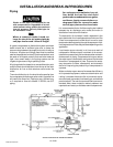
This compressor should be permanently mounted in
place on a level floor. Operate the air compressor in a
clean, dry and well ventilated area. The air intake filter
must be kept clear of obstructions which could reduce air
delivery of the air compressor. The air compressor
should be located at least 12" away from walls or other
obstructions that could interfere with the flow of air
through the fan bladed flywheel. The air compressor
crankcase and head are designed with fins to provide
proper cooling.
The flywheel side of the outfit should be placed toward
the wall and protected with a totally enclosed belt guard.
In no case should the flywheel be closer than 12 to 18
inches from the wall or other obstruction that will interfere
with the flow of air through the fan bladed flywheel. The
area should allow space on all sides for air circulation
and for ease of normal maintenance. Keep the outfit
away from areas which have dirt, vapor and volatile fumes
in the atmosphere which may clog and gum the intake
filter and valves, causing inefficient operation. Where this
is not practical a remote air intake is recommended.
If humidity is high, an air filter can be installed to
remove excessive moisture. Closely follow instruc-
tions packaged with the filter for proper installation. It
must be installed as close as possible to the acces-
sory.
The air compressor should be as near to air outlets as
possible in order to avoid long pipe lines. Do not place
the air compressor where heat is excessive.
Air Compressor Anchoring
Methods
THE PUMP ASSEMBLY DOES NOT PRO-
VIDE ADEQUATE STABILITY OR SUPPORT
FOR LIFTING THE UNIT. IF THE OUTFIT
MUST BE MOVED, USE THE TANK FOR
LIFTING.
VIBRATION CAN WEAKEN THE AIR TANK
AND CAUSE AN EXPLOSION. THE COM-
PRESSOR MUST BE PROPERLY MOUNTED
AS ILLUSTRATED BELOW.
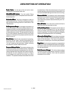
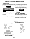
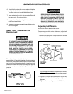
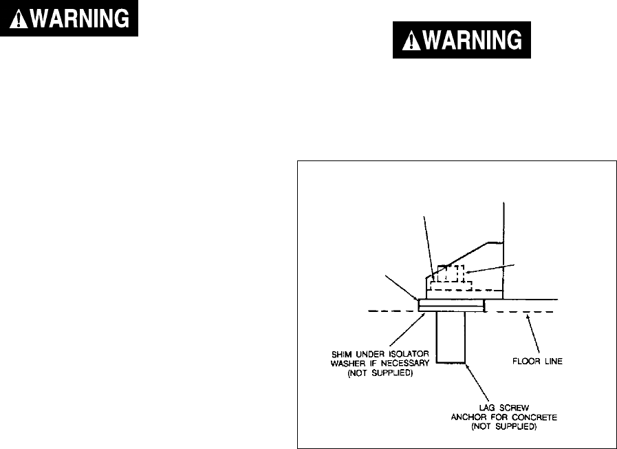
Anchoring of Horizontal Unit
Horizontal Units
Horizontal air compressors must be bolted to the floor.
Bolting holes are provided in the base feet. Mount the
air compressor on a solid, level foundation. Support
compressor weight evenly on all four feet. Solid shims
may be used if necessary.
ISOLATOR
WASHER
(supplied)
Location of the Air Compressor
Note
Where a remote air intake is used, en-
large the size of the air intake piping by
one pipe size for each 10 feet of length.
FLAT WASHER
LAG SCREW
(NOT SUPPLIED)
TORQUE TO
5 TO 10 FT-LB