


English
9
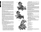
dealer at extra cost. Support long workpieces using any
convenient means such as sawhorses or similar devices to
keep the ends from dropping.
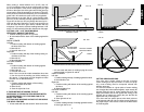
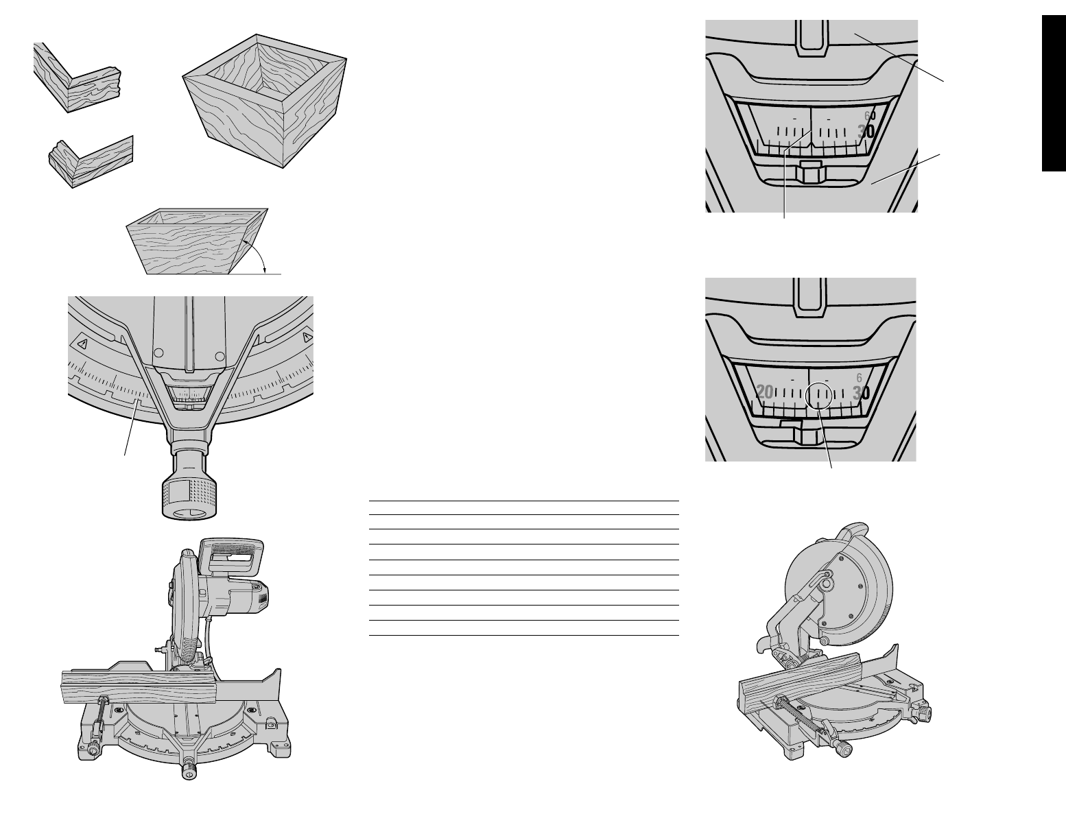
CUTTING PICTURE FRAMES, SHADOW BOXES AND
OTHER FOUR SIDED PROJECTS
To best understand how to make the items listed here, we
suggest that you try a few simple projects using scrap
wood until you develop a “FEEL” for your saw.
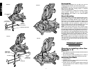
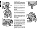
Your saw is the perfect tool for mitering corners like the one
shown in Figure 17. Sketch A in Figure 17 shows a joint
made by using the bevel adjustment to bevel the edges of
the two boards at 45 degrees each to produce a 90 degree
corner. For this joint the miter arm was locked in the zero
position and the bevel adjustment was locked at 45
degrees. The wood was positioned with the broad flat side
against the table and the narrow edge against the fence.
The cut could also be made by mitering right and left with
the broad surface against the fence.
CUTTING TRIM MOLDING AND OTHER FRAMES
Sketch B in Figure 17 shows a joint made by setting the
miter arm at 45 degrees to miter the two boards to form a
90 degree corner. To make this type of joint, set the bevel
adjustment to zero and the miter arm to 45 degrees. Once
again, position the wood with the broad flat side on the
table and the narrow edge against the fence.
The two sketches in Figure 17 are for four side objects
only.
As the number of sides changes, so do the miter and bevel
angles. The chart below gives the proper angles for a vari-
ety of shapes.
(The chart assumes that all sides are of equal length.) For
a shape that is not shown in the chart, use the following
formula. 180 degrees divided by the number of sides
equals the miter or bevel angle.
- EXAMPLES -
NO. SIDES ANGLE MITER OR BEVEL
445°
536°
630°
7 25.7°
8 22.5°
920°
10 18°
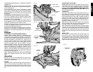
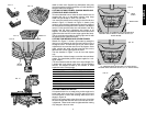
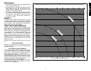
CUTTING COMPOUND MITERS
A compound miter is a cut made using a miter angle and a
bevel angle at the same time. This is the type of cut used
to make frames or boxes with slanting sides like the one
shown in Figure 18.
NOTE: If the cutting angle varies from cut to cut, check that
the bevel clamp knob and the miter lock knob are secure-
ly tightened. These knobs must be tightened after making
any changes in bevel or miter.
FIG. 17
FIG. 18
FIG. 19
A.
B.
ANGLE “A”
0
5
15
20
25
30
35
10
15
20
25
30
22.5
31.62
22.5
31.62
75
70
65
60
55
75
70
65
60
85
90
80
1
1
2
1
1
2
FIG. 20
MITER
SCALE
FIG. 21
1
1
2
1
1
2
70
25
65
0
20
70
25
65
1
1
2
1
1
2
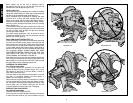
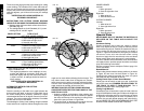
FIG. V1
FIG. V2
MITER ARM
CENTER MARK ON VERNIER SCALE ALIGNS WITH
DESIRED WHOLE ANGLE ON MITER SCALE (24°
RIGHT MITER)
1/4° VERNIER MARK ALIGNS WITH CLOSET WHOLE
DEGREE MARK ON MITER SCALE (24 1/4° RIGHT MITER)
KERF
PLATE
A
L
W
A
Y
S
A
D
J
U
S
T
F
E
N
C
E
P
R
O
P
E
R
L
Y
B
E
F
O
R
E
U
S
E
FIG. 22