


English
6
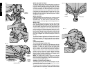
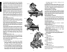
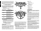
BEVEL SQUARE TO TABLE
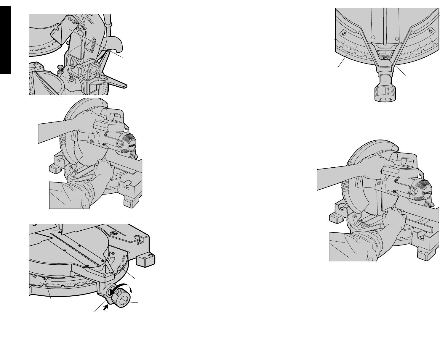
To align the blade square to the rotary table, lock the arm
in the down position. Place a square against the blade tak-
ing care to not have the square on top of a tooth, as shown
in Figure 11. Loosen the Bevel Clamp Knob so that you
can move the Bevel Arm. Move the Bevel Arm as neces-
sary so that the blade is at zero degrees bevel to the table.
If the Bevel Arm needs adjustment, loosen the lock nut on
the right side Bevel Stop as shown in Figure 12, and adjust
the stop screw as necessary. Hold the stop screw in place
and tighten the lock nut.
BEVEL POINTER
If the bevel pointer does not indicate zero, loosen the screw
that holds it in place and move the pointer as necessary.
SUGGESTION: The bevel pointer is quite thick and for
accuracy’s sake set the top edge so that it aligns with zero.
BEVEL STOP
To set the 45 degree bevel stop, first loosen the left side
fence clamping knobs and slide the left side fence as far
as it will go to the left. Move the arm to the left until it stops
on the left bevel stop screw. If the bevel pointer does not
indicate exactly 45 degrees, loosen the left side bevel stop
lock nut and turn the screw downwards. Move the arm to
the left and tighten the bevel clamp knob firmly when the
bevel pointer indicates exactly 45 degrees. Adjust the left
side bevel stop screw upwards until it firmly touches the
bevel stop. Retighten the nut while holding the screw from
turning.
To achieve 3 degree right bevel or 48 degree left bevel, the
stop screws must be adjusted to allow the arm to move to
the desired location. The bevel stops will need readjust-
ment to the zero and 45 degree positions after cuts are
made.
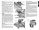
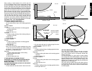
FENCE ADJUSTMENT
Turn Off and Unplug the Miter Saw
In order that the saw can bevel to a full 48 degrees left, the
left side of the fence can be adjusted to the left to provide
clearance. To adjust the fence, loosen the plastic knob
shown in Figure 13 and slide the fence to the left. Make a
dry run with the saw turned off and check for clearance.
Adjust the fence to be as close to the blade as practical to
provide maximum workpiece support, without interfering
with arm up and down movement. Tighten the knob
securely. When the bevel operations are complete, don’t
forget to relocate the fence to the right.
NOTE: The guide groove, shown in Figure 14, of the left
side fence can become clogged with sawdust. If you notice
that it is becoming clogged, use a stick or some low pres-
sure air to clear the guide groove.
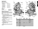
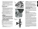
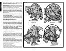
GUARD ACTUATION AND VISIBILITY
The blade guard on your saw has been designed to auto-
matically raise when the arm is brought down and to lower
over the blade when the arm is raised.
The guard can be raised by hand when installing or remov-
ing saw blades or for inspection of the saw. NEVER RAISE
FIG. 7
LOWER
GUARD
45
45
40
5
0
35
5
5
30
60
25
6
5
20
70
15
7
5
45
4
5
4
0
5
0
35
55
3
0
60
0
5
15
20
25
30
35
10
15
20
25
30
35
22.5
31.62
22.5
31.62
75
70
65
6
0
55
75
70
65
60
5
5
85
90
80
1
1
2
1
1
2
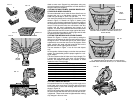
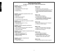
FIG. 9
MITER
CLAMP
KNOB
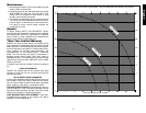
FIG. 10
MITER
SCALE
POINTER
FIG. 8
MITER
SCALE
ADJUSTMENT SCREW
(three of these)
MITER LATCH
FIG. 11