


a module may have only one cell in a two-cell tray. For
example, a 46 volt system will consist of eleven full mod-
ules and one single-cell module.Assemblies can be rotat-
ed 180° for proper polarity location.
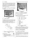
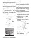
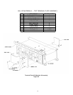
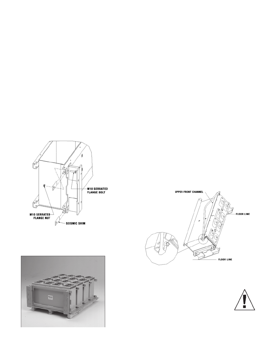
8.1.1 Bottom Supports (I-beams)
Locate bottom I-beam supports and M10 serrated flange
bolts and nuts. I-beam supports and seismic shims should
be attached to the appropriate module assembly shown
on the layout/wiring diagram prior to removal from ship-
ping pallet. Consult layout/wiring diagram for proper loca-
tion of positive/negative terminals relative to I-beam.
NOTE: Failure to use seismic shims (on systems where
seismic shims are indicated) will result in the
assembly not meeting seismic certification crite-
ria.
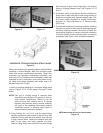
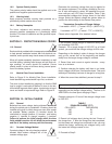
Secure I-beam support to a module channel as shown in
Figures 7 & 8, with access slots outward.
Torque hardware to 47 Newton-meters (35 Ft-Lbs) using
insulated tools. The side of the I-beam will be approxi-
mately 3.2mm (.125”) away from the end of the channels.
I-BEAM
HARDWARE INSTALLATION
Figure 7
I-BEAM SUPPORT INSTALLED
Figure 8
Similarly, install the remaining I-beam on the other side of
the module.
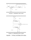
8.1.2 Handling
The module/I-beam assembly may now be removed from
the pallet using methods outlined in Section 6.5. See
Figures 4 and 5. Remaining modules may be removed in
a similar manner.
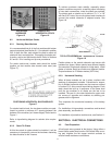
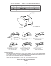
8.1.3 Tip Over Procedure
In order to stack modules in the horizontal position, refer
to Figures 9 through 11 to perform the tip-over procedure.
The module/I-Beam assembly tip-over should be per-
formed first. This procedure can be performed using a
portable boom crane or fork lift in conjunction with the lift-
ing straps and lifting shackles supplied.
A. Install lifting strap using lifting shackles in channel base
holes at each end of module upper front channel as
shown in Figure 9.
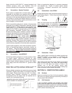
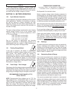
B. Center the lifting hook onto strap and lift until strap is
under tension and raises bottom of module from floor
surface.
C. While exerting manual force on the upper front of
module, lower hoist until module is in horizontal posi-
tion. See Figures 10 and 11.
D. After tip over procedure when module is horizontal,
install the four lifting shackles and two lifting straps as
shown in Figure 12 to position and handle battery in
horizontal position.
TIP-OVER PROCEDURE - SHACKLE-STRAP USAGE
Figure 9
NOTE (for Figure 9):
1) One strap with shackles used for
tip-over procedure.
2) Observe channel hole used as well as
direction of shackle insertion.
3) Tip over procedure for single modules only.
12