


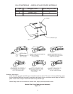
10.2 System Polarity Labels
The system polarity labels should be applied next to the
positive and negative system terminals.
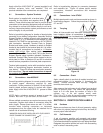
10.3 Warning Label
Apply pressure sensitive warning label provided on a
prominently visible module side or end.
10.4 Battery Nameplate
For future reference and warranty protection, apply
pressure sensitive nameplate on a prominently visible
module. Fill in date of installation and the specified capac-
ity and rate.
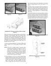
SECTION 11: PROTECTIVE MODULE COVERS
11.0 General
Each module is provided with a transparent protective cover
to help prevent accidental contact with live electrical con-
nections, and to provide easy visual access to the system.
When all system assembly has been completed, as well
as initial testing, including initial charge and cell float volt-
age readings, all covers should be installed. Covers
should remain in place at all times during normal opera-
tion of the battery system.
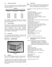
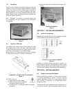
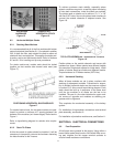
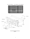
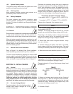
11.1 Module Clear Cover Installation
Refer to Figure 21 for Module Clear Cover installation.
Install standoff legs and standoff keys first, as shown.
The cover is then installed by grasping it so that the GNB
logo is upright. Locate slots at bottom of cover to the bot-
tom standoff legs and slide in place. Locate holes at top of
cover and install to top standoff legs. Refer to Figure 21.
SECTION 12: INITIAL CHARGE
12.0 General
Batteries lose some charge during shipment as well as
during the period prior to installation. A battery should be
installed and given its initial charge as soon after receipt
as possible. Battery positive (+) terminal should be
connected to charger positive (+) terminal and battery
negative (-) terminal to charger negative (-) terminal.
Failure to perform the initial charge within the time
limits stated in section 4.2 will affect the performance
and life of the battery and may void the warranty.
12.1 Constant Voltage Method
Constant voltage is the only charging method
allowed. Most modern chargers are of the
constant voltage type.
Determine the maximum voltage that may be applied to
the system equipment. This voltage, divided by the num-
ber of cells connected in series, will establish the maxi-
mum volts per cell (VPC) that is available. Table C lists
recommended voltages and charge times for the initial
charge. Select the highest voltage the system allows to
perform the initial charge in the shortest time period.
Temperature Correction of Charger Voltage
V corrected = V25°C - ((T actual -25°C) x (.0055 V/°C))
or
V corrected = V77°F - ((T actual - 77°F) x .003V/°F))
Please refer to Appendix A for standard values.
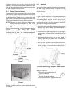
1. Set constant voltage charger to maximum setting with-
out exceeding 2.35 VPC.
Example: For a target charge of 2.35 VPC on a 24-cell
system, you would set the charger voltage to 56.4 volts.
Depending on the batteryʼs state of charge, the charger
may go into current limit at the beginning and decline
slowly once the target charge voltage is reached.
2. Record time and current at regular intervals – every
hour as a minimum.
3. Continue charging the battery until there is no further
drop in charge current over 3 consecutive hours. This could
take days if the battery has been in storage for a long time.
4. When the current has stabilized, proceed to step 2.
1. Continue the charge for the time listed in Table C
depending on the charger voltage setting. The time is IN
ADDITION to the time spent charging in Step 1.
Example: charge for 12 hours if the charger voltage is set
to 2.35 VPC.
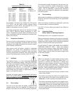
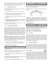
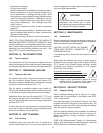
TABLE C
EQUALIZE CHARGE (77°F)
CELL VOLTS TIME (HOURS)
2.30 24
2.33 18
2.35 12
2. Record cell voltages hourly during the last 3 hours of
the charge time. If, after the charge time has completed,
but the lowest cell voltage has continued to rise, you may
extend the charge, monitoring cell voltages hourly, until
the lowest cell voltage ceases to rise.
3. Proceed to Step 3.
STEP 2
STEP 1
17