


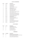
TABLE A
TEMPERATURE EFFECTS ON LIFE
Maximum Annual Maximum Percent
Average Battery Battery Reduction
Temperature Temperature In Battery Life
25°C (77°F) 50°C (122°F) 0%
30°C (86°F) 50°C (122°F) 30%
35°C (95°F) 50°C (122°F) 50%
40°C (104°F) 50°C (122°F) 66%
45°C (113°F) 50°C (122°F) 75%
50°C (122°F) 50°C (122°F) 83%
For example: If a battery has a design life of 20 years at
77°F (25°C), but the actual annual average battery
temperature is 95°F (35°C), the projected life of the
battery is calculated to be only 10 years.
The battery temperature shall not be allowed to exceed
50°C (122°F). Minimum battery temperature is -40°C
(-40°F). Temperature records shall be maintained by the
user in accordance with the maintenance schedule pub-
lished in this manual.
5.3 Temperature Variations
Sources of heat or cooling directed on portions of the bat-
tery can cause temperature variations within the strings
resulting in cell voltage differences and eventual compro-
mise of battery performance.
Heat sources such as heaters, sunlight or associated
equipment can cause such temperature variations.
Similarly, air conditioning or outside air vents may cause
cell string temperature variations. Every effort should be
made to keep temperature variations within 3°C (5°F).
5.4 Ventilation
The Absolyte battery is a Valve Regulated Lead Acid
(VRLA) low maintenance design. Tests have confirmed
that under recommended operating conditions in station-
ary applications, 99% or more of gases generated are
recombined within the cell. In most cases, no special
ventilation and or battery room is required. Consult your
local building and fire codes for requirements that may
apply to your specific location.
Hydrogen and oxygen gases can be vented to the atmos-
phere under certain conditions. Therefore, the battery should
never be installed in an air-tight enclosure. Sufficient pre-
cautions must be taken to prevent excessive overcharge.
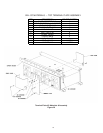
5.5 Floor Loading
The floor of the area where the battery system is to be
installed should have the capability of supporting the
weight of the battery as well as any auxiliary equipment.
The total battery weight will depend on the cell size, num-
ber of cells, as well as module configuration involved.
Consult layout/wiring diagram for the battery system
weight Prior to installation, a determination should be
made that the floor integrity is adequate to accommodate
the battery system.
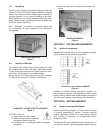
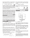
5.6 Floor Anchoring
Where seismic conditions are anticipated, floor anchoring
should be provided. Such anchoring is the responsibility
of the user.
Where non-seismic conditions are anticipated, anchoring
is recommended for maximum stability.
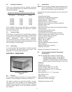
Four 9/16” (14.3 mm) holes are provided in the I-Beam for
anchoring.
5.7 Connecting Cables:
Battery System to Operating Equipment
The Absolyte cell is a UL recognized component.
Battery performance is based on the output at the battery
terminals. Therefore, the shortest electrical connections
between the battery system and the operating equipment
results in maximum total system performance.
DO NOT SELECT CABLE SIZE BASED ON CURRENT
CARRYING CAPACITY ONLY. Cable size selection
should provide no greater voltage drop between the bat-
tery system and operating equipment than necessary.
Excess voltage drop will reduce the desired support time
of the battery system.
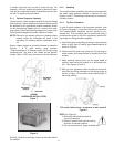
5.7.1 Paralleling
Where it is necessary to connect battery strings in paral-
lel in order to obtain sufficient load backup time, it is
important to minimize the differences in voltage drop
between the battery strings in parallel in order to promote
equal load sharing upon discharge. Therefore, equal
resistance of cable connections for each parallel string is
important. When paralleling multiple strings to a load or
common bus, please follow these guidelines:
• Each parallel string must have the same number of cells
(same string voltage).
• The cables connecting the positive and negative termi-
nals of each string to the load (or bus) should be of the
same size (i.e. same capacity/cross-sectional area).
• The cables connecting the positive and negative termi-
nals of each string to the load (or bus) should be of the
same length. Choose the shortest cable length that will
connect the battery string that is furthest from the load,
and cut all cables used to connect each string to the load
to this same length.
9