


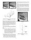
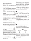

TIP-OVER PROCEDURE MODULE AFTER TIP-OVER
Figure 10 Figure 11
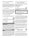
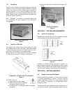
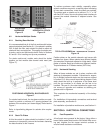
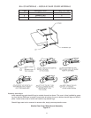
HORIZONTAL STACKING SHACKLE-STRAP USAGE
Figure 12
Where floor anchoring is required, position module/I-Beam
assembly in desired location. Mark floor through I-beam
holes and remove module/base assembly. Install floor
anchoring and reposition module/base assembly over
anchoring. Prior to installing nuts and washers, check that
assembly is level in both axes. Level using shims provid-
ed. When level, fasten assembly and torque nuts to 47
Newton-meters (35 Ft-Lbs).
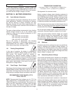
In order to complete stacking of a horizontal single stack
refer to Figures 12 to 15 and steps A through C listed
below.
NOTE: The use of leveling shims is required when
assembling any Absolyte GX system in order to
meet seismic requirements. Failure to use the
shims to level each module and to fill spaces
between tray channels during module assembly
will result in the assembly not meeting seismic
certification criteria. In extreme cases, stack to
stack connectors cannot be installed.
A. Using Section 6.5 and 8.1.3 and the layout/wiring
diagram, position the next module on top of first so that
channels of each mate with one another. Use drift pins
to align channel holes. Make sure channel ends and
sides of the upper and lower modules are flush.
Remove lifting straps and install M10 serrated flange
bolts and nuts in open holes, finger tight. Use leveling
shims to fill gaps between trays. See Figures 13, 14
and 15.
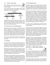
B. At this time, check to see that the first two modules are
plumb front to back and side to side using wooden or
plastic level together with plywood straight edge. This
is to insure proper alignment for module interconnec-
tion later on. Torque hardware to 47 Newton-meters
(35 Ft-Lbs).
C. Proceed with stacking of remaining modules, checking
that stack is plumb in both axes as stacking progress-
es before torquing hardware. Be certain to check the
layout/wiring diagram for correct horizontal orientation
to provide proper polarity interconnection as stacking
progresses. See Figure 16 for completed assembly.
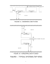
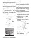
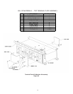
HANDLING AND STACKING HORIZONTAL MODULES
Figure 13
HARDWARE INSTALLATION SEQUENCE
Figure 14
13