


Apply a thin film of NO-OX-ID “A” grease (supplied) to all
terminal surfaces, bolts, and washers. This will
preclude oxidation after connections are completed.
9.1 Connections - System Terminals
Each system is supplied with a terminal plate
assembly for the positive and negative termi-
nations. These should always be used to provide proper
connection to the operating equipment and cell terminals.
Any attempt to connect load cables directly to cell termi-
nal may compromise battery system performance as well
as the integrity of cell post seals.
Refer to layout/wiring diagram for location of terminal plate
assembly in your battery configuration. Assemble Terminal
Support Bracket to module channel using hardware indi-
cated, items 3, 4, 5, 6. Hardware will be located in a bag
labeled K17-417240P for top termination or K17417256 for
side termination. Assemble Terminal Plate to Support
Bracket and battery posts. Hardware to attach to Support
bracket is also located in the terminal plate kit. It is recom-
mended that all connections be torqued to 11 Newton-
meters (100 in-Lbs). After making cable connections,
assemble Terminal Plate Covers, Items 7 & 8, to the Terminal
Support Bracket using hardware indicated. Hardware to
assemble Terminal Plate Covers will be located in the ter-
minal plate kit. Refer to Sections 9.0 and 9.2 for electrical
contact surface preparation of terminal plate components.
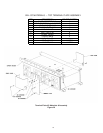
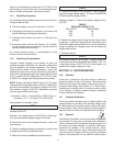
Terminal plate assembly varies with termination location.
Refer to layout/wiring diagram termination location on
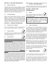
your battery. Figure 20 shows top termination assembly
with instructions. Do not make connections to operat-
ing system at this time.
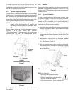
9.2 Connections - Inter-MODULE
Consult layout/wiring diagram for correct quantity of lead-
tin plated copper connectors required for each
connection. Follow procedure in Section 9.0 and brighten
lead-tin plated surfaces coming in contact with copper
posts. Apply a thin film of NO-OX-ID “A” grease to these
areas.
NOTE: Apply a minimum amount of grease to cover the
surface. As a rule: "If you can see it, it's too much".
Where multiple connectors are required across any single
connection, brighten both sides of connectors along the
entire length. Grease these areas as well. It is recom-
mended when installing connectors on horizontal
arrangements that the upper bolts be installed first to
reduce risk of accidental shorting.
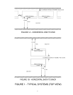
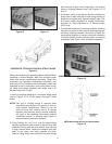
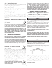
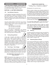
Refer to layout/wiring diagram for connector placement
and materials list. Figure 19 shows typical module
connections, intrastack connections and interstack
connections.
9.3 Connections - Inter-STACK
Multiple stacks end to end are interconnected as shown in
layout/wiring diagram. Follow the procedures in Sections
9.1 and 9.3.
9.4 Torquing
When all inter-module and inter-stack connections have
been installed, tighten all connections to 11.3 Newton-
meters (100 in-Lbs) Use insulated tools. Recheck connec-
tions after the initial charge due to heating during charge.
STACK CONNECTIONS
Figure 19
9.5 Connection - Check
Again, visually check to see that all module terminals are
connected positive (+) to negative (-) throughout the
battery. Positive terminals have red cap. Negative
terminals have black cap.
Also measure the total open circuit voltage from terminal
plate to terminal plate. This should be approximately
equal to 2.14 volts times the number of cells in the
system, e.g., a 24 cell system would read:
24 x 2.14v = 51.4 volts. An incorrect voltage reading may
mean connectors were installed incorrectly.
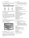
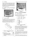
SECTION 10: IDENTIFICATION LABELS
10.0 Surfaces
Make sure surfaces are free of dirt and grease by wiping
with clean, dry wipers (isopropyl alcohol may be used) to
ensure proper label adhesion.
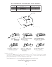
10.1 Cell Numerals
A set of pressure sensitive cell numerals and system
polarity labels are supplied and should be applied at this time.
Cell numerals should be applied to the cell being identified.
Designate the positive terminal cell as #1 with succeeding
cells in series in ascending order.
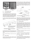
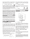
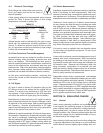
WASHERS SHOULD BE INSTALLED WITH THE CURVED
EDGE TOWARD THE CONNECTORS.
BOLT WASHER CONNECTOR POST
15