


1. The initial charge is complete. Charger voltage can
now be reduced to float voltage setting per Section 13.2.
For a target float charge of 2.25 VPC on a 24-cell system,
you would set the charger voltage to 54 volts.
SECTION 13: BATTERY OPERATION
13.0 Cycle Method of Operation
In cycle operation, the degree of discharge will vary for dif-
ferent applications. Therefore, the frequency of recharg-
ing and the amount of charge necessary will vary.
Generally, Absolyte GX cells require approximately 105-
110% of the ampere-hours removed to be returned to a
full state of charge.
The upper voltage settings recommended, given that the
maxium charge current is 5% of the nominal C100
Amp-hour rating and the ambient temperature is 25°C
(77°F), are as follows:
2.28 ± 0.02 VPC @ 0-2% DOD
2.33 ± 0.02 VPC @ 3-5% DOD
2.38 ± 0.02 VPC @ >5% DOD
Due to the variety of applications and charging
equipment (particularly in photovoltaic systems) it is
recommended that you contact a GNB representative
when determining proper recharge profiles.
13.1 Floating Charge Method
In this type of operation, the battery is connected in
parallel with a constant voltage charger and the critical
load circuits. The charger should be capable of
maintaining the required constant voltage at battery
terminals and also supply a normal connected load where
applicable. This sustains the battery in a fully charged
condition and also makes it available to assume the emer-
gency power requirements in the event of an AC power
interruption or charger failure.
13.2 Float Charge - Float Voltages
Following are the float voltage ranges recommended for the
Absolyte Battery System. Select any “volts per cell” (VPC)
value within the range listed that will result in the series
string having an average volts per cell equal to that value.
RECOMMENDED FLOAT RANGE (@77°F)
2.23 to 2.25 VPC
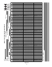
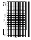
NOTE: Recommended float voltages are for 77°F. For
other temperatures a compensation factor of .003 V/°F
(.0055 V/°C) per cell is recommended. The minimum volt-
age is 2.20 VPC, temperature correction does not apply
below this voltage. The maximum voltage is 2.35 VPC,
temperature correction does not apply above this voltage.
TEMPERATURE CORRECTION
V corrected = V25°C - (( T actual-25°C) x ( .0055V/°C)) or
V corrected = V77°F - ((T actual-77°F) x (.003V/°F))
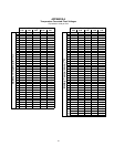
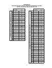
See Appendix A for standard values.
Modern constant voltage output charging equipment is
recommended for the floating charger method of opera-
tion of GNB Absolyte batteries. This type of charger, prop-
erly adjusted to the recommended float voltages and fol-
lowing recommended surveillance procedures, will assist
in obtaining consistent serviceability and optimum life.
After the battery has been given its initial charge (refer to
Section 12), the charger should be adjusted to provide the
recommended float voltages at the battery terminals
.
Do not use float voltages higher or lower than those rec-
ommended. Reduced capacity or battery life will result.
Check and record battery terminal voltage on a regular
basis. Monthly checks are recommended. See Section
15.0, Records. If battery float voltage is above or below
the correct value, adjust charger to provide proper voltage
as measured at the battery terminals
.
13.3 Recharge
All batteries should be recharged as soon as possible fol-
lowing a discharge with constant voltage chargers. To
recharge in the shortest period of time, raise the charger
output voltage to the highest value which the connected
system will permit. Do not exceed the voltages and times
listed in Table E in Section 14.2.
13.4 Determining State-of-Charge
If the normal connected load is constant (no emergency
load connected), the following method can be used to
determine the approximate state-of-charge of the battery.
The state-of-charge can be identified to some degree by
the amount of charging current going to the battery. When
initially placed on charge or recharge following a dis-
charge, the charging current, read at the charger amme-
ter, will be a combination of the load current plus the cur-
rent necessary to charge the battery. The current to the
battery will start to decrease and will finally stabilize when
the battery becomes fully charged. If the current level
remains constant for three consecutive hours, then this
reflects a state-of-charge of approximately 95 to 98%. For
most requirements, the battery is ready for use.
If the normal connected load is variable (i.e. telecommuni-
cations), the following method may be used to check the
state-of-charge of the battery. Measure the voltage across
a pilot cell (See Section 15 for definition of pilot cell). If the
voltage is stable for 24 consecutive hours, the battery
reflects a state of charge of approximately 95%.
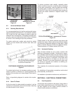
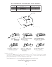
STEP 3
19