


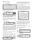
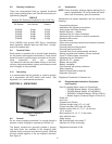
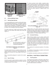
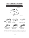
INSTALLING COMPLETED
HARDWARE HORIZONTAL STACK
Figure 15 Figure 16
8.2 Horizontal-Multiple Stacks
8.2.1 Stacking Base Modules
It is recommended that all of the first modules with bottom
supports attached (see Section 8.1.1) be placed in position
first. A chalk line floor mark should be used to assure all
stacks will be in a straight line. This applies for stacks end-
to-end or end-to-end and back-to-back. Refer to Sections
6.5 and 8.1.3 for handling and tip over procedures.
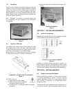
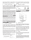
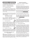
For stacks end-to-end, module ends should be butted
together so that module side channel ends meet (see
Figure 17).
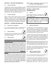
POSITIONING HORIZONTAL BASE MODULES
Figure 17
For stacks back-to-back, the two base modules are posi-
tioned to provide a minimum 4.5” spacing between the
bottoms of the modules (not I-beam edges). Refer back to
Figure 1.
Refer to layout/wiring diagram for seismic shim require-
ments.
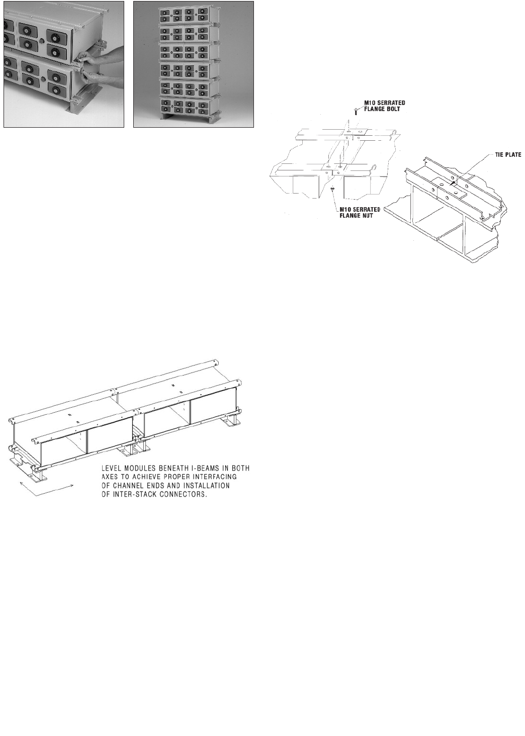
8.2.2 Stack Tie Plates
At this time stack tie plates should be installed. It will be
necessary to temporarily remove the hardware fastening
the base modules to the I-beams.
To achieve maximum stack stability, especially where
seismic conditions may exist, as well as proper interfacing
of inter-stack connections, metal tie plates are provided.
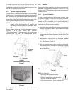
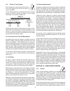
The plates used on stacks end to end are 3” x 1” x 1/8”
with two 9/16” holes. Use one tie plate at each interface to
connect the module channels of adjacent stacks. See
Figure 18.
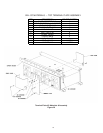
TIE PLATE ASSEMBLIES - HORIZONTAL STACKS
Figure 18
Position plates on the module channels and secure with
hardware as shown. Where stacks have different heights
(for example a 3 high stack adjacent to 4 high stack), install
plates on shorter stack top module and adjacent module.
Torque hardware to 47 Newton-meters (35 Ft-Lbs).
8.2.3 Horizontal Stacking
When all base modules are set in place, continue with
stacking of subsequent modules. Procedures for assem-
bly of multiple horizontal stacks are the same as outlined
in section 8.1.3. Also consult layout/wiring diagram. Each
stack should be built up in sequence to the same level
until the top modules in all stacks are the last to be
installed. The use of a line chord attached to upper mod-
ule corners of opposite end modules as stacking pro-
gresses aids in alignment.
This completes the mechanical assembly of the battery
system.
For installation of intermodular connections and terminal
plate assembly, see Section 9.
For installation of protective module cover, see Section 11.
SECTION 9: ELECTRICAL CONNECTIONS
9.0 Post Preparation
All cell posts were greased at the factory. Using either a
brass bristle suede shoe brush or 3M Scotch Brite scour-
ing pad, brighten the flat copper terminal surfaces to
ensure lowest resistance connections.
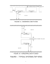
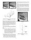
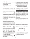
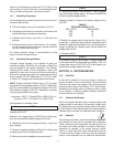
TOP MODULE
BASE MODULE
14