


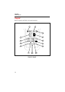

Input Connections
9
Input Connections
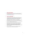
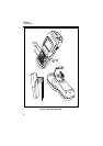
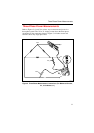
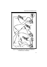
Refer to Figure 4 for a view of the two-input measurement scheme. To
measure voltage, insert the red test lead in “V” and the black test lead in
“COM.” Current measurement uses a BNC connector attached to “CURRENT
PROBE.” Connect “V” and “COM” to measure only voltage; connect
“CURRENT PROBE” to measure only current. Make all three connections for
power measurements.
Observe the following connection guidelines:
• Current
Clamp the Current Probe around the desired phase or neutral conductor.
Make sure the arrow on the probe points toward the load (phase) or the
source (neutral). The Tester is set up for use with an 80i-500s Current
Probe. If you use another probe, you must make a selection change in the
Configuration Screen.
• Voltage: 3-phase, 4-Wire
Connect the red test lead to the desired phase voltage; connect the black
test lead to neutral.
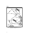
• Voltage: 3-phase, 3-Wire, example
Connect the red test lead to the phase conductor used by the Current
Probe; connect the black test lead to another phase.
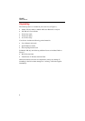
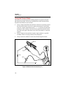
Using the Voltage Test Leads
The TL-24 Test Lead and AC-20 Test Clip combination (Figure 1), which
allows for hands-free voltage measurements, is preferred when you are also
using the Current Probe.
Note
Figure 4 shows suggested test lead and current probe usage.