


10 308842
Motor Brush Replacement
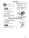
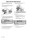
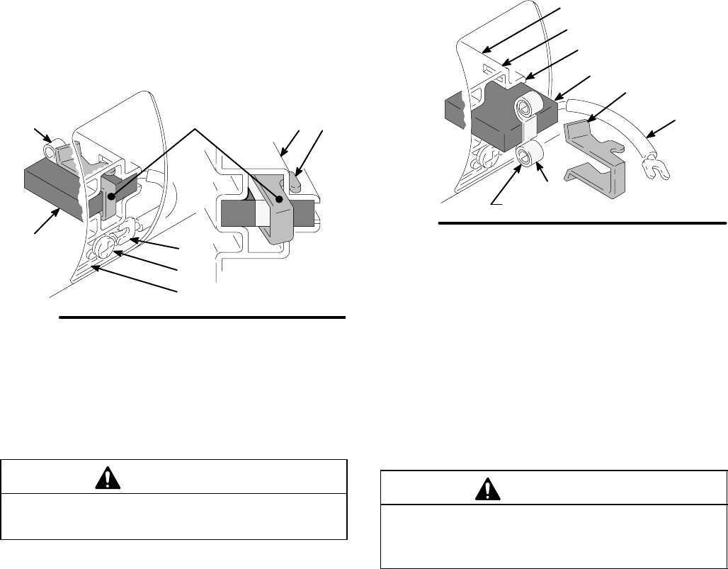
4. Fig. 5. Push in 110816 spring clip (A) to release
hooks (B) from brush holder (C). Pull out spring
clip.
5. Fig. 5. Loosen terminal screw (D). Pull brush lead
(E) away, leaving motor lead (F) in place. Remove
brush (G) and spring (H).
Fig. 5
H
E
D
F
G
A
01227
BC
6. Inspect commutator for excessive pitting, burning
or gouging. A black color on commutator is normal.
Have commutator resurfaced by a qualified motor
repair shop if brushes wear too fast.
Motor Brush Installation
CAUTION
When installing brushes, follow all steps carefully to
avoid damaging parts.
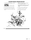
7. Fig. 6. Install new brush (G) with lead in long slot
(J) of brush holder (C).
8. Fig. 5. Slide brush lead (E) under washer of termi-
nal screw (D) and tighten screw. Be sure motor
lead (F) is connected at terminal screw.
9. Fig. 6.Place spring (H) on brush (G).
10. Fig. 6. Install spring clip (A). Push down to hook
short slots (K) in brush holder (C).
Fig. 6
G
K
J
C
NOTE SPRING COIL DIRECTION
A
01227
E
H
11. Repeat for other side.
12. Test brushes.
a. Remove pump connecting rod pin.
b. With sprayer OFF, turn pressure control knob
fully counterclockwise to minimum pressure.
Plug in sprayer.
c. Turn sprayer ON. Slowly increase pressure
until motor is at full speed.
CAUTION
Do not run sprayer dry for more than 30 seconds
while checking brushes to avoid damaging displace-
ment pump packings.
13. Install brush inspection covers and gaskets.
14. Break in brushes.
a. Operate sprayer 1 hour with no load.
b. Install connecting rod pin.