


psi
bar
MPa
13308842
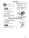
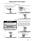
Pressure Control Repair
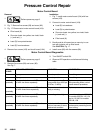
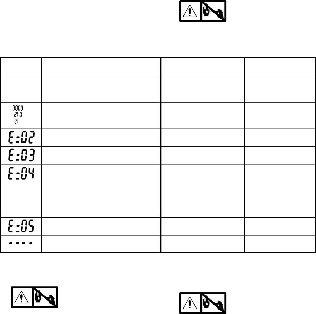
Digital Display Messages
1. Lift lid on pressure control cover and view display.
2. Observe display and reference following table:
3.
No display does not mean
that sprayer is not pressur-
ized. Relieve pressure before repairing;
page 3.
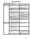
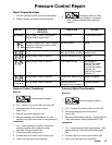
DISPLAY SPRAYER
OPERATION
INDICATION ACTION
No Display Sprayer stops. Power is not applied.
Sprayer may be pressurized.
Loss of power Check power source
Sprayer is pressurized. Power is applied.
(Pressure varies with tip size and pres-
sure control setting.)
Normal operation Spray
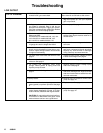
Sprayer stops. Power is applied. Pressure greater than
4500 psi (310 bar, 31 MPa).
Replace pressure
control board
Sprayer stops. Power is applied. Pressure transducer faulty Replace
Sprayer stops. Power is applied. Line voltage too high Set voltage to:
230 VAC for models
232144, 145, 154
110 VAC for models
232148, 158
100 VAC for models
232156, 157
Sprayer stops. Power is applied. Locked rotor. Motor can not
turn
Repair or replace
Sprayer stops. Power is applied. Pressure less than
200 psi (14 bar, 1.4 MPa)
Increase pressure
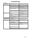
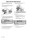
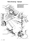
Pressure Control Transducer
Removal
1.
Relieve pressure; page 3.
2. Fig. 7. Remove five screws (28) and cover (82).
3. Disconnect lead (E) from motor control
board (104).
4. Remove strain relief bushing (116).
5. Remove pressure control transducer (31) and
packing o-ring (59) from control housing plate (89).
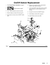
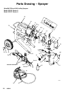
Installation
1. Fig. 7. Install packing o-ring (59) and pressure
control transducer (31) in control housing
plate (89). Torque to 30–35 ft-lb.
2. Install strain relief bushing (116).
3. Connect lead (E) to motor control board (104).
4. Install cover (82) with five screws (28).
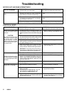
Pressure Adjust Potentiometer
Removal
1.
Relieve pressure; page 3.
2. Fig. 7. Remove five screws (28) and cover (82).
3. Disconnect lead (D) from motor control
board (104).
4. Remove potentiometer knob (81), sealing shaft nut
(106) and pressure adjust potentiometer (105).
Installation
1. Fig. 7. Install pressure adjust potentiometer (105),
sealing shaft nut (106) and potentiometer knob
(81).
2. Connect lead (D) to motor control board (104).
3. Install cover (82) with five screws (28).