


12 308842
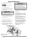
Pressure Control Repair
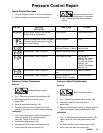
Motor Control Board
Removal
1.
Relieve pressure; page 3.
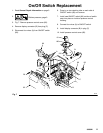
2. Fig. 7. Remove five screws (28) and cover (82).
3. Fig. 17. Disconnect at motor control board (104):
D Filter board (8).
D Six motor leads: two yellow, two violet, black
(+) and red (–).
D Lead (D) from potentiometer.
D Lead (E) from transducer.
4. Remove four screws (102) and circuit board (104).
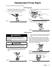
Installation
1. Fig. 7. Install motor control board (104) with four
screws (102).
2. Connect to motor control board (104):
D Lead (E) to transducer.
D Lead (D) to potentiometer.
D Six motor leads: two yellow, two violet, black
(+) and red (–).
D Filter board (8).
3. Bundle and tie all loose wires so none lay in con-
tact with inductor coil on filter board.
See CAUTION, Fig. 17.
4. Install cover (82) with five screws (28).
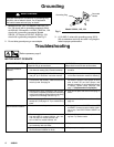
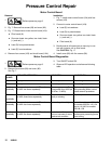
Motor Control Board Diagnostics
1.
Relieve pressure; page 3.
2. Remove five screws (28) and cover (82).
See Fig. 7.
3. Turn ON/OFF switch ON.
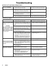
4. Observe LED operation and reference following
table:
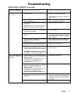
LED
BLINKS
SPRAYER OPERATION INDICATES WHAT TO DO
Once Sprayer runs Normal operation Do nothing
Twice Sprayer runs Normal operation Do nothing
Two times
repeatedly
Sprayer shuts down and LED continues
to blink two times repeatedly
Run away pressure. Pres-
sure greater than 4500 psi
(310 bar, 31 MPa).
Replace motor control board.
See preceding Motor control
board removal procedure.
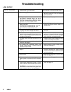
Three times
repeatedly
Sprayer shuts down and LED continues
to blink three times repeatedly
Pressure transducer is
faulty or missing
Replace pressure transducer
Four times
repeatedly
Sprayer shuts down and LED continues
to blink four times repeatedly
Line voltage is too high Lower line voltage to 230 VAC
for models 232144, 145, 154
and to 110 VAC for models
232148, 158
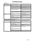
Five times
repeatedly
Sprayer shuts down and LED continues
to blink five times repeatedly
Locked rotor. Motor can
not turn because of some
mechanical condition.
Clear obstruction and replace
broken parts preventing motor
from turning