


5308842
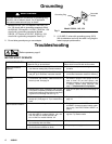
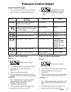
Troubleshooting
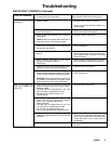
MOTOR WON’T OPERATE (Continued)
TYPE OF PROBLEM
WHAT TO CHECK
If check is OK, go to next check
WHAT TO DO
When check is not OK refer to this column
Basic Electrical Problems
(continued)
1. That motor leads are securely fastened and
properly mated.
1. Replace loose terminals; crimp to leads. Be
sure terminals are firmly connected.
Clean circuit board terminals. Securely re-
connect leads.
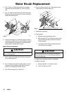
2. For loose motor brush lead connections and ter-
minals. See page 9.
2. Tighten terminal screws. Replace brushes if
leads are damaged. See page 9.
3. Brush length which must be 1/2 in. minimum.
See page 9.
NOTE: Brushes do not wear at the same rate on
both sides of motor. Check both brushes.
3. Replace brushes. See page 9.
4. For broken or misaligned motor brush springs.
Rolled portion of spring must rest squarely on
top of brush. See page 9.
4. Replace spring if broken. Realign spring with
brush. See page 9.
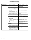
5. Motor brushes for binding in brush holders. See
page 9.
5. Clean brush holders. Remove carbon with
small cleaning brush. Align brush leads with
slot in brush holder to assure free vertical
brush movement.
6. Motor armature commutator for burn spots,
gouges and extreme roughness.
See page 9.
6. Remove motor and have motor shop resur-
face commutator if possible. See page 16.
7. Motor armature for shorts using armature tester
(growler) or perform spin test. See page 9.
7. Replace motor. See page 16.
8. Motor control board (104) by performing motor
control board diagnostics on page 12. If diag-
nostics indicate, substitute with a good board.
CAUTION: Do not perform this check until mo-
tor armature is determined to be good. A bad
motor armature can burn out a good board.
8. Replace with new pressure control board
(104). See page 12.
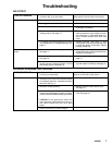
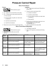
Refer to wiring diagram on
page 23 to identify test
points (TP).
1. Power supply cord (79). Connect volt meter be-
tween TP1 (neutral) and TP2. Plug in sprayer.
Meter must read:
210–250 VAC for models 232144, 145, 154.
100–120 VAC for models 232148, 158.
90–110 VAC for models 232156, 157.
Unplug sprayer.
1. Replace power supply cord.
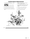
2. ON/OFF switch (80). Connect volt meter be-
tween TP1 and TP3 terminal on ON/OFF
switch. Plug in sprayer and turn ON.
Meter must read:
210–250 VAC for models 232144, 145, 154.
100–120 VAC for models 232148, 158.
90–110 VAC for models 232156, 157.
Turn off and unplug sprayer. Reconnect TP3
2. Replace ON/OFF switch. See page 11.
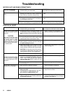
3. Motor thermal cutoff switch. Turn sprayer OFF.
Check for continuity between TP4 and TP5 with
ohmmeter.
3. If thermal switch is open (no continuity), allow
motor to cool. If switch remains open after
motor cools, replace motor. If thermal switch
closes after motor cools, correct cause of
overheating.
4. All terminals for damage or loose fit. 4. Replace damaged terminals and reconnect
securely.