


4 308842
Grounding
WARNING
Improper installation or alteration of grounding plug
results in risk of electric shock, fire or explosion
that could cause serious injury or death.
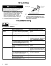
1. Models 232144, 145, 154 require a 230 VAC, 50
Hz, 10A circuit with a grounding receptacle. Mod-
els 232148, 158 require a 110 VAC, 50/60 Hz, 15A
circuit with a grounding receptacle. Models
232156, 157 require a 100 VAC, 50/60 Hz, 15A
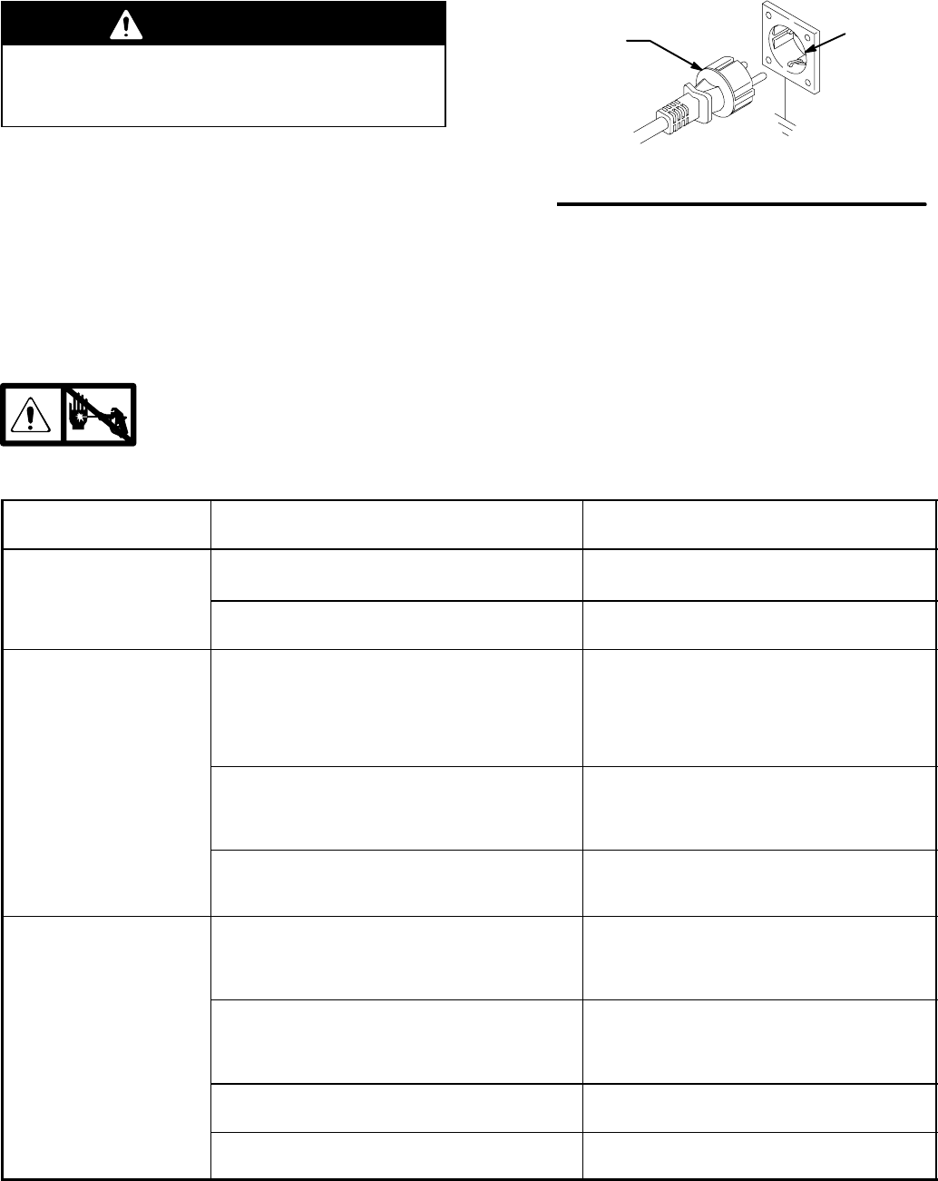
circuit with a grounding receptacle. See Fig. 2.
2. Do not alter ground prong or use adapter.
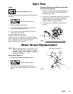
Fig. 2
Grounding Plug
Grounded
Outlets
Model 232144, 145, 154
3. A 12 AWG, 3 wires with grounding prong, 300 ft
(90 m) extension cord may be used. Long lengths
reduce sprayer performance.
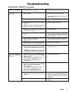
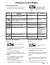
Troubleshooting
Relieve pressure; page 3.
MOTOR WON’T OPERATE
TYPE OF PROBLEM
WHAT TO CHECK
If check is OK, go to next check
WHAT TO DO
When check is not OK refer to this column
Basic Fluid Pressure
Problems
1. Pressure control knob setting. Motor will not run
if at minimum setting (fully counterclockwise).
1. Slowly increase pressure setting to see if mo-
tor starts.
2. For clogged spray tip or fluid filter. Refer to sepa-
rate gun, tip, or fluid filter instruction manual.
2. Relieve pressure, refer to separate gun, tip,
or fluid filter instruction manual for cleaning.
Basic Mechanical
Problems
1. For frozen or hardened paint in pump (64). Use
a screwdriver and carefully rotate fan at back of
motor by hand. See page 9.
1. Thaw sprayer if water or water-based paint
has frozen in sprayer. Place sprayer in warm
area to thaw. Do not start sprayer until
thawed completely. If paint hardened (dried)
in sprayer, replace pump packings. See
page 17 (Displacement Pump Repair).
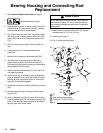
2. Displacement pump connecting rod pin (66).
Pin must be completely pushed into connecting
rod (63) and retaining spring (68) must be firmly
in groove of connecting rod. See Fig. 12.
2. Push pin into place and secure with spring re-
tainer.
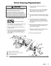
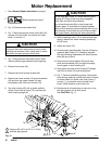
3. For motor damage. Remove drive housing as-
sembly (67). See page 15. Try to rotate fan by
hand.
3. Replace motor (73) if fan won’t turn. See
page 16.
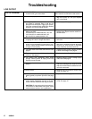
Basic Electrical Problems
1. Pressure control safety circuit. 2. Turn pressure control ON/OFF switch to OFF
to RESET. If pressure control safety contin-
ues to trip, see ELECTRICAL SHORT on
page 8.
2. Electrical supply. Meter must read:
210–250 VAC for models 232144, 145, 154.
100–120 VAC for models 232148, 158.
90–110 VAC for models 232156, 157.
2. Reset building circuit breaker; replace build-
ing fuse. Try another outlet.
3. Extension cord for damage. Check extension
cord continuity with volt meter.
3. Replace extension cord.
4. Sprayer power supply cord (79) for damage
such as broken insulation or wires.
4. Replace power supply cord.