


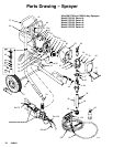
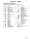
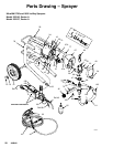
8054A
16
20
49
67
67b
51
67a
90
90
34
26
20
54
22
73
2016
70
40
A
30
10
85
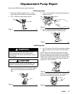
Fig. 10
98
79
1
2
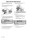
Torque to 90–100 in-lb (10.2–11.3 Nm)
Liberally apply grease
2
1
1
36
16 308842
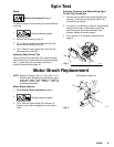
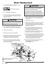
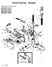
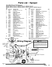
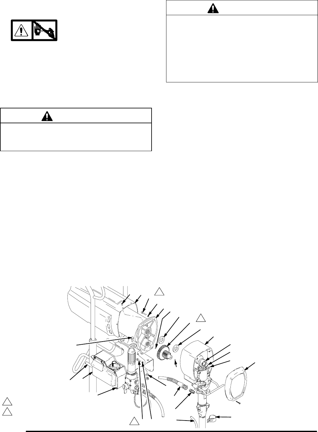
Motor Replacement
1. Read General Repair Information on page 3.
2.
Relieve pressure; page 3.
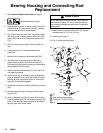
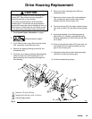
3. Fig. 10. Remove motor shield (54).
4. Fig. 7. Remove pressure control cover (82). Dis-
connect six motor leads: two yellow, two violet,
black (+) and red (–).
CAUTION
Always pull the motor leads one at a time to avoid
loosening the terminals, which could result in a bad
connection and poor sprayer performance.
5. Fig. 7. Remove strain relief (99) and pull motor
wires bundle through pressure control opening.
6. Remove front cover (49).
7. Remove two drive housing screws (26).
8. Remove two lower screws (16) and lockwashers
(20) and then two upper screws (16) and
lockwashers (20) from front of motor (73).
9. Tap drive housing (67) with a plastic mallet to
loosen it from front of motor (73), and then pull
drive housing straight off.
CAUTION
Do not drop gear cluster (51) when removing drive
housing (67). Gear cluster may stay engaged in
motor front end bell or drive housing.
Do not lose thrust balls (90) or drop thrust balls
between gears. If thrust balls are caught between
gears and not removed, serious damage will occur to
drive housing. If thrust balls are not in place at each
end of gear cluster, bearings will wear prematurely.
10. While supporting motor (73) to keep sprayer from
tipping, remove four motor mounting screws (8).
Lift off motor.
11. Install new motor (73).
12. Liberally apply approximately 4 ounces of bearing
grease to gear cluster (51). Grease is supplied
with drive housing replacement kit. Be sure thrust
balls (90) are in place.
13. Place bronze-colored washer (67b) and then
silver-colored washer (67a) on shaft protruding
from big gear in drive housing (67).
14. Align gears and push drive housing (67) straight
onto front of motor (73) and locating pins.
15. Fig. 7. Continue assembling sprayer. Feed motor
wires through opening in pressure control. Connect
six motor leads: two yellow, two violet, black (+)
and red (–), to pressure control printed circuit
board. Install pressure control cover (A).
16. Bundle and tie all loose wires so none lay in con-
tact with inductor coil on filter board.
See CAUTION, Fig. 17.