


Optional Hose Position
18 312666R
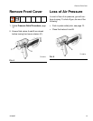
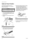
Optional Hose Position
Fluid inlet swivel fittings point to rear. If
desired, these positions can be changed so
hoses point downward.
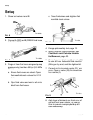
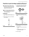
1. Follow Pressure Relief Procedure, page
17. Also relieve system pressure, see pro-
portioner manual.
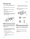
2. Disconnect air (D) and remove fluid mani-
fold (M).
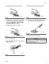
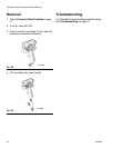
3. Disconnect fluid hoses from inlet swivels
(A, B). Remove fluid valve assemblies.
Remove plugs from optional inlets (P).
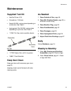
4. Apply thread sealant to plugs (1e), elbows
(35), and male threads of fluid valve
assemblies. Install elbows (35) in optional
inlets, facing down. Install fluid valve
assemblies in elbows. Be sure to install A
fluid assembly in A side. Install plugs where
swivels had been. Torque all parts to
235-245 in-lb (26.6-27.7 N•m).
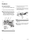
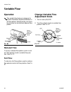
5. Connect A and B hoses to A and B swivels.
6. Attach fluid manifold. Connect air. Return
gun to service.
CAUTION
To prevent cross-contamination of gun’s wet-
ted parts, do not interchange A component
(isocyanate) and B component (resin) parts.
F
IG
. 21
F
IG
. 22
TI11330a
M
D
TI11329a
A
B
P
F
IG
. 23
TI12085a
1e