Repair
38 312666R
Mix Chamber and Side Seal
Assemblies
See Models/Mix Chamber Selection Guide,
page 4, for available mix chamber sizes.
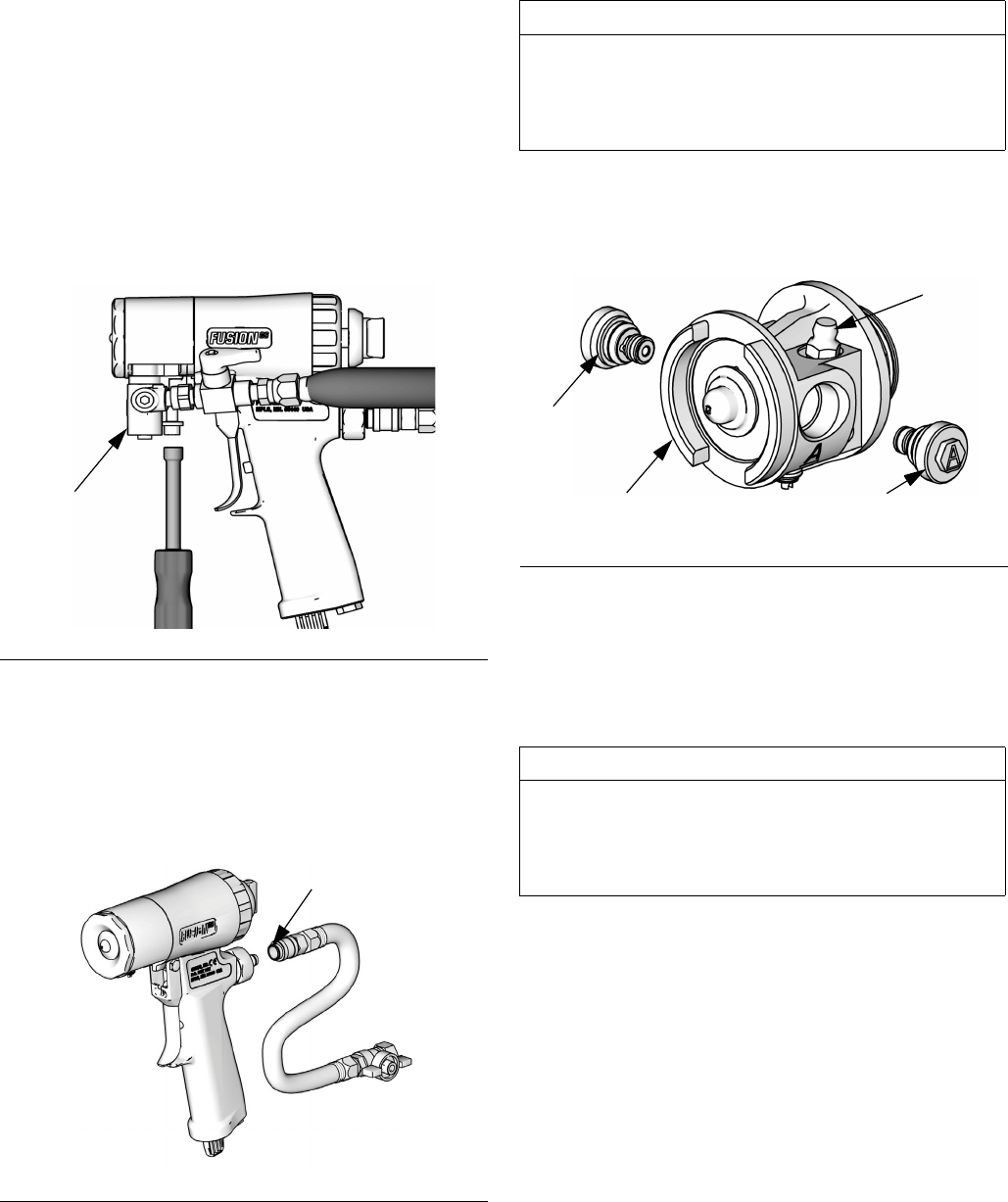
1. Follow Pressure Relief Procedure, page
17.
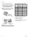
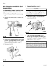
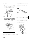
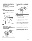
2. Remove fluid manifold (M). Leave air con-
nected.
3. Flush gun to remove residual A and B com-
ponents. See Flush Gun, page 26. Follow
Pressure Relief Procedure, page 17.
4. Disconnect air (D).
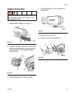
5. Remove Front End, page 36.
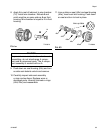
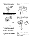
6. Use hex nut driver to remove side seal
assemblies (42, 43).
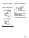
7. Push on front of mix chamber (14) to
loosen. Pull mix chamber out rear of fluid
housing (F). Inspect for damage and Clean
Impingement Ports, page 29.
F
IG
. 49
F
IG
. 50
TI12095a
M
TI12086a
D
CAUTION
To prevent cross-contamination of side seal
assemblies, do not interchange A compo-
nent and B component parts. The A compo-
nent assembly is marked with an A.
F
IG
. 51
CAUTION
To prevent cross-contamination of the gun’s
wetted parts, mix chamber is marked with an
A and a notch on back edge. Be sure the A
side of mix chamber is on the A side of gun.
TI12096b
B
A
2a
43
42
F


