


Service
WARNING
Fluid Packing Replacement
To reduce the risk of serious injury, including fluid
injection, and splashing in the eyes or on the skin,
or injury from moving parts or electric shock, al-
ways follow the Pressure Relief Procedure
Warning on page 10 before servicing any part of
the gun or system.
1.
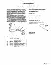
If leakage occurs at the back of the fluid needle
(5), replace the needle packings (47) and inspect
the needle shaft. See Fig. 7.
2.
Remove the air cap retainer (25), air cap (27),
fluid tip (28), and air separator (32).
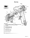
NOTE: Follow the Service Notes in Fig. 7 when reas-
sembling the gun. Also refer to the parts drawing on
page 14 for parts not shown in Fig. 7.
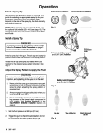
Air Valve Service
1. Remove the trigger (3) and valve cap (11). See
Fig. 7.
2. Unscrew the needle nut (49) while holding the
flats of the air valve (52) stem with a long nose
pliers.
ECAUTION
To prevent leakage, be careful not to scratch the
3.
4.
5.
6.
Remove the spring (10) and air valve (52). See
Fig. 7.
If there is air leakage at the air valve (52), unscrew
the packing nut (50) and carefully remove the
u-cup packing (51). Replace packing if worn or
damaged. When reinstalling, be sure the u-cup
faces inward.
If leakage occurs internally or the front of the gun
leaks air when untriggered, clean and inspect the
air valve and the spring for wear or damage.
Replace as needed.
For best air valve life, lubricate the external air
valve shaft (point A) with light oil after each day’s
use.
3.
4.
5.
6.
7.
8.
9.
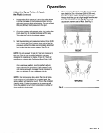
Pull the trigger to back the fluid needle ball off the
seat. Unscrew the diffuser (30). Inspect the fluid
gasket (33) for any visible damage. Remove and
replace if necessary.
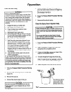
Remove the trigger (3).
Remove the hex nut (21) from the fluid needle (5)
while holding the square part of the fluid needle.
Pull the fluid needle (5) and compression spring
(24) from the front of the gun.
To remove the old packings, insert the packing
removal tool (55) into the front of the gun and
screw it into the packings (47). Pull the packings
from the front of the gun. Clean and inspect all
parts for wear or damage, replacing as needed.
Insert the new packings (47) onto the needle (5)
shaft as shown in Detail D of Fig. 7.
Install the fluid needle (5) with the packings (47).
Be careful not to damage the packings.
10. Screw the hex nut (21) to the bottom thread of the
needle. Torque it to 4 to 6 in-lb (5 to 8 N*m); do
not over tighten.
11. Install the trigger. Lubricate the diffuser threads.
Pull the fluid needle (5) back with the trigger while
screwing the diffuser (30) back into the gun.
Torque it to 23 to 27 ft-lb (37 to 32 Nom).
12. Reassemble the air separator (32)) fluid tip (28),
air cap (27), and air cap retainer (25).
12 307-947