


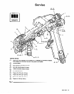
Installation
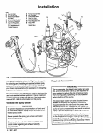
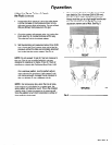
KEY
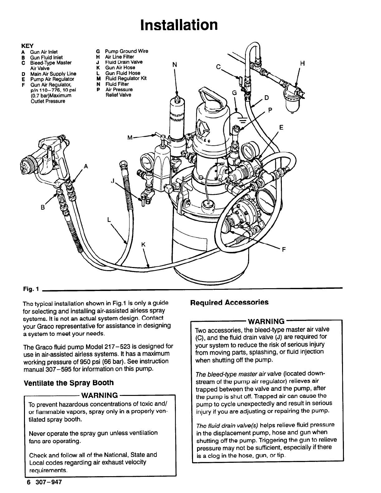
A Gun Air Inlet
B Gun Fluid Inlet
C Bleed-Type Master
Air Valve
D Main Air Supply Line
E Pump Air Regulator
F Gun Air Regulator,
p/n 110-776, 10 psi
(0.7 bar)Maximum
Outlet Pressure
G Pump Ground Wire
H Air Line Filter
J Fluid Drain Valve
K Gun Air Hose
L Gun Fluid Hose
M Fluid Regulator Kit
N Fluid Filter
P Air Pressure
Relief Valve
Fig. 1
The
typical installation shown
in
Fig.1
is only a guide
for selecting and installing air-assisted airless spray
systems. It is not an actual system design. Contact
your Grace representative for assistance in designing
a system to meet your needs.
The Grace fluid pump Model 217-523 is designed for
use in air-assisted airless systems. It has a maximum
working pressure of 950 psi (66 bar). See instruction
manual 307-595 for information on this pump.
Ventilate the Spray Booth
WARNING
To prevent hazardous concentrations
of
toxic and/
or flammable vapors, spray only in a properly ven-
tilated spray booth.
Never operate the spray gun unless ventilation
fans are operating.
Check and follow all of the National, State and
Local codes regarding air exhaust velocity
requirements.
6 307-947
Required Accessories
WARNING
Two accessories, the bleed-type master air valve
(C), and the fluid drain valve (J) are required for
your system to reduce the risk of serious injury
from moving parts, splashing, or fluid injection
when shutting off the pump.
The
bleed-type master air valve
(located down-
stream of the pump air regulator) relieves air
trapped between the valve and the pump, after
the pump is shut off. Trapped air can cause the
pump to cycle unexpectedly
and result in serious
injury if you are adjusting or repairing the pump.
The fluid drain
valve(s) helps relieve fluid pressure
in the displacement pump, hose and gun when
shutting off the pump. Triggering the gun to relieve
pressure may not be sufficient, especially if there
is a clog in the hose, gun, or tip.