


Installation
ConnectConnect
Connect
SolenoidSolenoid
Solenoid
ValveValve
Valve
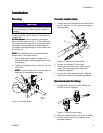
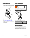
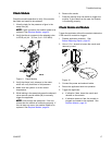
1. Connect 1/4 in. diameter air supply tubing to a
clean, dry, and non-lubricated air supply and to
the push-to-connect air inlet tting (L).
Figure 6 Air Inlet Fitting
2. Connect solenoid valve (J) to 24 VDC signal.
See Connect Triggering Device, page 10.
NOTE:NOTE:
NOTE:
A 6 mm tube tting is included with the
applicator. The tting can be changed using a 5
mm Allen wrench.
ConnectConnect
Connect
TriggeringTriggering
Triggering
DeviceDevice
Device
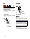
All GM100 valves use a 24 VDC solenoid valve.
Improper electrical connection can result in electric
shock. All electrical wiring must be done by a
qualied electrician and comply with all local codes
and regulations.
Figure 7 Solenoid Valve Electrical Connector
StandardStandard
Standard
WiringWiring
Wiring
ColorsColors
Colors
TerminalTerminal
Terminal
CableCable
Cable
FunctionFunction
Function
M8M8
M8
Plus (+) 24V Supply
Brown
Minus ( - )
Return Blue/Black
BeforeBefore
Before
UsingUsing
Using
EquipmentEquipment
Equipment
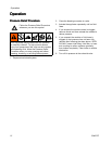
The equipment was tested with canola oil, which is
left in the uid passages to protect parts. To avoid
contaminating your uid with oil, prime the equipment
with hot melt until all of the oil is pushed out before
using the equipment. See Flush, page 11.
10334627D