


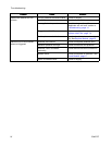
Repair
ReplaceReplace
Replace
SolenoidSolenoid
Solenoid
ValveValve
Valve
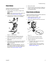
1. Disable the applicator. See
Before Beginning Repair, page 20.
2. Turn off the air supply to the solenoid valve.
3. Disconnect the M8 solenoid electrical connector
(N).
4. Disconnect air line from air tting (L).
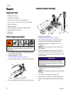
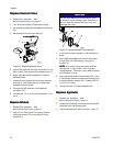
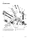
Figure 15 Replace Solenoid Valve
5. Loosen the solenoid valve set screw with a 3 mm
Allen wrench, then remove the solenoid valve (J).
6. Apply high temperature grease to o-rings on
solenoid tubes.
7. Install the new solenoid valve into the manifold,
then use a 3 mm Allen wrench to tighten the
solenoid valve set screw.
8. Connect the M8 solenoid valve electrical
connector (N).
9. Connect the 1/4 in. air line to the solenoid. Turn
air on.
ReplaceReplace
Replace
ModuleModule
Module
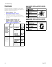
1. Disable the applicator. See
Before Beginning Repair, page 20.
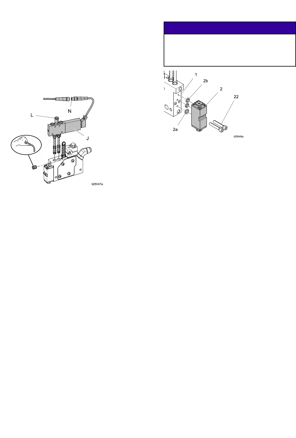
2. Use a 3 mm Allen wrench to remove the two
mounting screws (22) and module (2) from
manifold (1).
NOTICENOTICE
NOTICE
Do not allow adhesive to enter the air ports,
to allow air to ow through valve. Adhesive in
the air ports will obstruct the ow of air and
damage the valve.
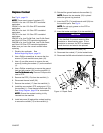
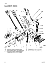
Figure 16 Remove Module From Manifold
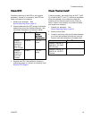
3. Verify that no glue is present in the manifold air
ports.
4. Apply high temperature lubricant to air section
o-rings (2b) and uid section o-ring (2a) in
module (2).
NOTE:NOTE:
NOTE:
Air section o-rings are brown and the
uid section o-ring is black. All o-rings are
uoroelastomer. The color is only used to identify
the difference in size.
5. Apply anti-seize to two screw threads (22). Use
a 3 mm Allen wrench to install new module (2) on
manifold with two screws (22). Torque to 28–32
in.-lb (3.2–3.6 N•m).
6. Connect cordset (17) to the heated hose.
ReplaceReplace
Replace
ApplicatorApplicator
Applicator
1. Disable the applicator. See
Before Beginning Repair, page 20.
2. Loosen the mounting bar clamp and remove the
applicator from the mounting bar.
3. Install new applicator. See Installation, page 9 .
24
334627D