


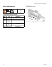
Component Identification
16 312062W
Component Identification
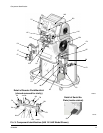
Key for F
IG
. 3
BA Component A Pressure Relief Outlet
BB Component B Pressure Relief Outlet
EC Heated Hose Electrical Connector
EM Electric Motor, Fan, and Belt Drive (behind shroud)
FA Component A Fluid Manifold Inlet (on left side of manifold
block)
FB Component B Fluid Manifold Inlet
FH Fluid Heater (behind shroud)
FM Reactor Fluid Manifold
FP Feed Inlet Pressure Gauge
FS Feed Inlet Strainer
FT Feed Inlet Temperature Gauge
FV Fluid Inlet Valve (B side shown)
GA Component A Outlet Pressure Gauge
GB Component B Outlet Pressure Gauge
HA Component A Hose Connection
HB Component B Hose Connection
HC Hydraulic Pressure Control
HP Hydraulic Pressure Gauge
LR ISO Lube Pump Reservoir
MC Motor Control Display
MP Main Power Switch
OP Overpressure Rupture Disk Assembly (on rear of A and B
pumps)
PA Component A Pump
PB Component B Pump
RS Red Stop Button
SA Component A PRESSURE RELIEF/SPRAY Valve
SB Component B PRESSURE RELIEF/SPRAY Valve
SC Fluid Temperature Sensor Cable
SN Serial Number Plate (one inside cabinet, one on right side
of cabinet)
SR Electrical Cord Strain Relief
TA Component A Pressure Transducer (behind gauge GA)
TB Component B Pressure Transducer (behind gauge GB)
TC Temperature Control Display
TD Oil Cooler