


Setup
26 312062W
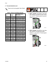
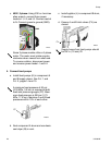
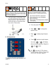
c. 400V, 3 phase: Using 5/32 or 4 mm hex
allen wrench, connect three power
leads to L1, L2, and L3. Connect neutral
to N. Connect green to ground (GND).
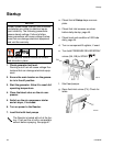
5. Connect feed pumps
a. Install feed pumps (K) in component A
and B supply drums. See F
IG
. 1 and
F
IG
. 2, pages 14 and 15.
b. Seal component A drum and use desic-
cant dryer (M) in vent.
c. Install agitator (L) in component B drum,
if necessary.
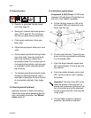
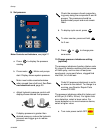
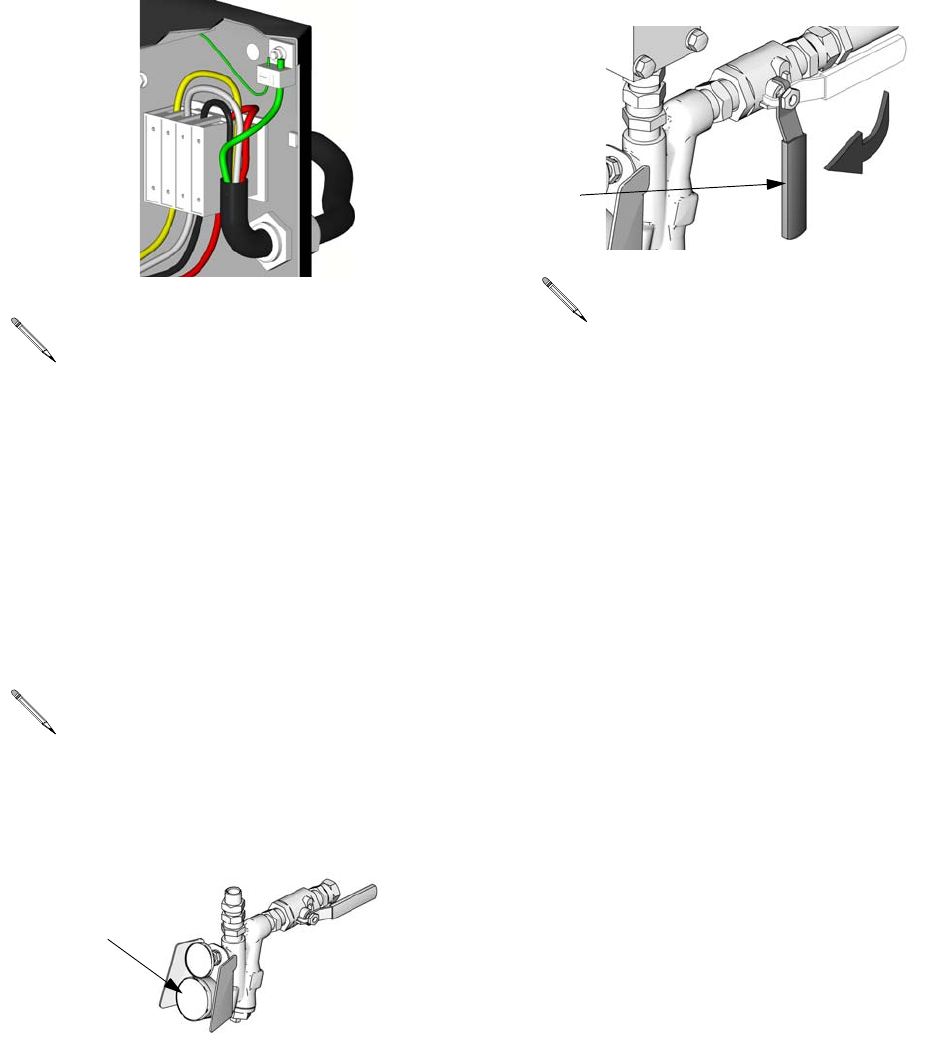
d. Ensure A and B inlet valves (FV) are
closed.
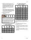
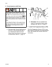
Some 3-phase models utilize a 3-phase
motor. The motor must rotate counter-
clockwise when viewed from shaft end.
To reverse rotation, disconnect power
and reverse power leads L1 and L2.
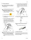
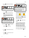
A minimum feed pressure of 50 psi
(0.35 MPa, 3.5 bar) is required at both
feed inlet pressure gauges (FP). Maxi-
mum feed pressure is 250 psi (1.75
MPa, 17.5 bar). Maintain A and B feed
pressures within 10% of each other.
L1
L2
GND
ti2725a
L3
N
FP
ti10006a
Supply hoses from feed pumps should
be 3/4 in. (19 mm) ID.
FV
ti9883a