


Setup
28 312062W
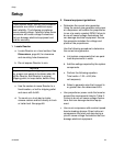
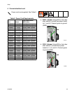
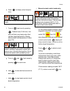
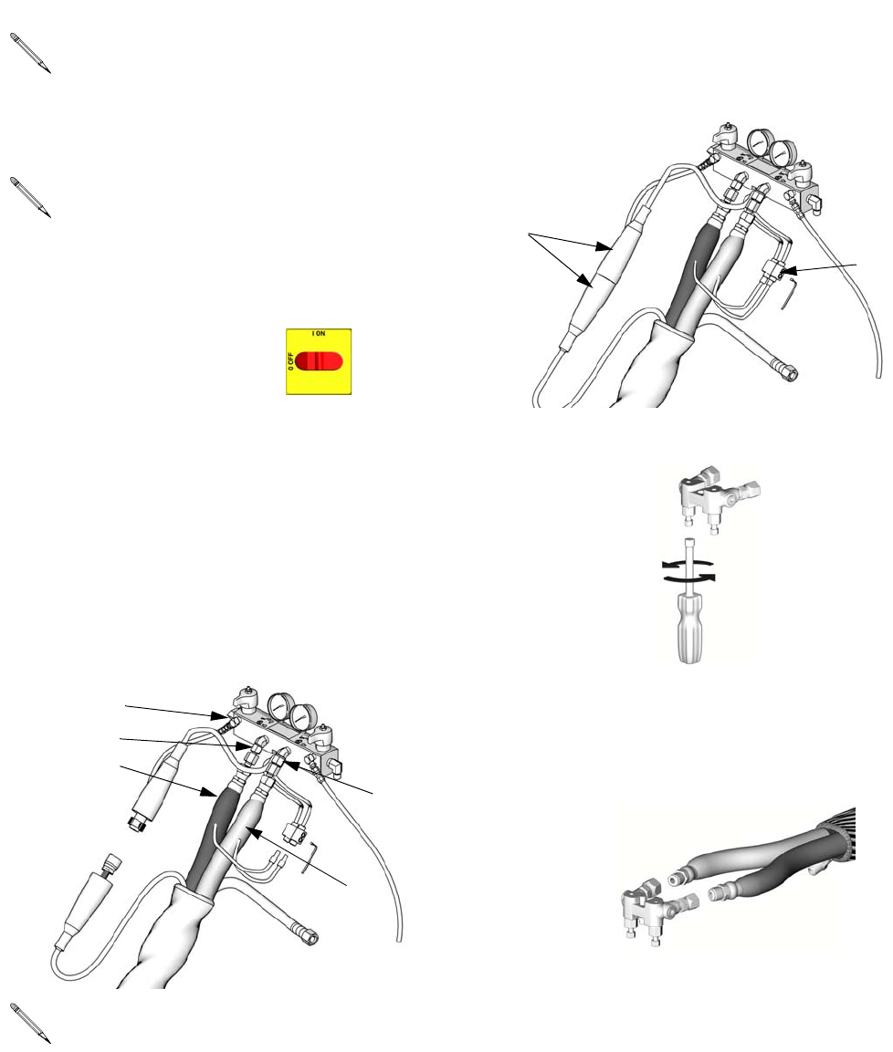
8. Connect heated hose
a. Turn main power OFF .
b. Assemble heated hose sections, FTS,
and whip hose.
c. Connect A and B hoses to A and B out-
lets on Reactor fluid manifold (FM).
Hoses are color coded: red for compo-
nent A (ISO), blue for component B
(RES). Fittings are sized to prevent con-
nection errors.
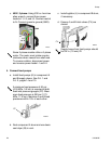
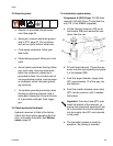
d. Connect cables (Y). Connect electrical
connectors (V). Be sure cables have
slack when hose bends. Wrap cable
and electrical connections with electri-
cal tape.
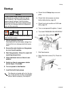
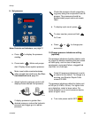
9. Close gun fluid manifold valves A and B
10.Connect whip hose to gun fluid mani-
fold
11.Pressure check hose
See hose manual. Pressure check for leaks. If
no leaks, wrap hose and electrical connections
to protect from damage.
See Heated Hose manual 309572 for
detailed instructions on connecting
heated hoses.
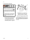
The fluid temperature sensor (C) and
whip hose (D) must be used with
heated hose, see page 27. Hose
length, including whip hose, must be 60
ft (18.3 m) minimum.
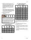
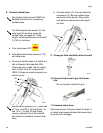
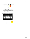
Manifold hose adapters (N, P) allow use
of 1/4 in. and 3/8 in. ID fluid hoses. To
use 1/2 in. (13 mm) ID fluid hoses,
remove adapters from fluid manifold
and install as needed to connect whip
hose.
FM
A
B
ti9878a
N
P
Do not connect manifold to gun.
ti9881a
V
Y
ti2411a
ti2417a