


32 308018
Service
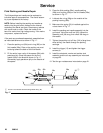
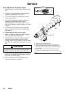
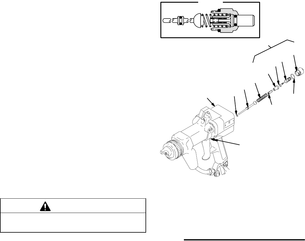
Fluid Adjustment Assembly Repair
1. Prepare the gun for service as instructed on page
24.
2. Using a 14 mm socket wrench, remove the fluid
adjustment assembly (45). See Fig. 21.
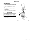
3. Turn the stem (45a) fully clockwise and remove
the sleeve stop (45e).
4. To completely disassemble the fluid adjustment
assembly, the sleeve stop (45e) must be
assembled back on to the stem (45a). Turn the
stem until the sleeve is protruding about 0.4 inches
(10 mm).
5. To remove the sleeve (45d), hold the cap (45c)
and turn the sleeve stop (45e) counterclockwise
with a wrench.
6. Remove the stem (45a) and o-ring (45b).
7. Repair or replace any damaged parts. Lubricate
the o-ring (45b) with petroleum jelly.
8. Carefully apply low strength (purple) Loctite or
equivalent thread sealant to the sleeve (45d)
external threads. Turn the sleeve in with the sleeve
stop (45e) until it bottoms out, then back it out 1/8
turn.
CAUTION
Do not allow Loctite to get onto the stem (45a) during
assembly or the stem will not turn after assembly.
9. Place the fluid adjustment assembly on the work-
bench with its threaded end facing down and allow
the Loctite to cure over night.
10. After the Loctite has cured, assemble the fluid
adjustment assembly into the gun.
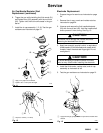
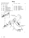
06631
Fig. 21
41
39
44
45c
40, 42
45a
45b
45d
23
7
45
45e
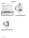
Lubricate o-rings with petroleum jelly
Carefully apply low strength (purple) Loctite or equivalent to
sleeve (45d) external thread. Turn sleeve in with sleeve stop
(45e) until it bottoms out, then back out 1/8 turn. Allow Loctite to
cure overnight.
Do not remove u-cup (42) unless damaged. Install with lips
facing into handle. Tighten packing nut (40) until it bottoms.
0636A
DETAIL