


Installation
10 311052E
Connect Fluid Line
1. Install a fluid filter and drain valve(s) close to the
pump's fluid outlet.
2. Install a fluid pressure regulator to control fluid pres-
sure to the gun.
3. Install a fluid shutoff valve to shut off the fluid supply
to the gun.
4. Install an in-line fluid filter on the gun fluid inlet (F) to
avoid clogging the spray tip with particles from the
fluid. See F
IG. 6.
5. In a circulating system, connect a grounded fluid
supply hose to the gun fluid fitting. Connect a
grounded return hose to the other port.
In a non-circulating system, remove the gun fluid
outlet fitting (G) and plug the outlet port with the
pipe plug (109) supplied.
Before connecting the fluid line, blow it out with air
and flush it with solvent. Use solvent that is compat-
ible with the fluid to be sprayed.
A fluid drain valve(s) is required in your system to
assist in relieving fluid pressure in the displacement
pump, hose and gun; triggering the gun to relieve
pressure may not be sufficient.
A fluid pressure regulator must be installed in the
system if the pump's maximum working pressure
exceeds the gun's maximum fluid working pressure
(see the front cover).
Some applications require fine-tuned control of fluid
pressure. You can control fluid pressure more accu-
rately with a fluid pressure regulator than by regu-
lating the air pressure to the pump.
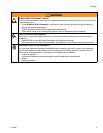
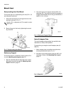
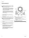
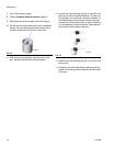
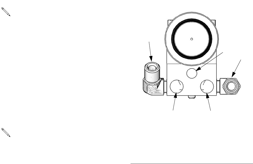
F
IG. 6: Side Mounted Manifold Ports
FAN
ATOM
CYL
Cylinder Air Inlet: accepts 1/4 in. (6.3 mm) O.D. tubing
Atomization Air Inlet: 1/4-18.6 npsm
Fan Air Inlet: 1/4-18.6 npsm
Fluid Inlet: 1/4-18 nptf or #5 JIC (1/2-20 unf)
Fluid Outlet (circulating gun only): 1/4-18 nptf or #5 JIC
(1/2-20 unf)
KEY
C
D
E
F
G
C
F (or G)
G (or F)
E
D
TI8113a