


Service
311052E 23
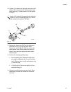
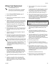
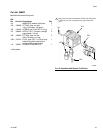
Diffuser Seat Replacement
1. Perform Pressure Relief Procedure, page 12.
2. Remove gun from manifold.
3. Remove the air cap retaining ring (8), air cap (30),
and spray tip (9).
4. Trigger the gun (or remove cap (27) and springs (28,
29)) to pull the needle housing off the seat while you
unscrew the diffuser (10) from the gun body (1).
5. Inspect the o-rings (10d, 10e, 10f) in place. Care-
fully remove the o-rings from the diffuser housing
(10) and replace if necessary.
6. Remove the seat nut (10c), seat (10b) and seat gas-
ket (10g) (Carbide seat only) using a 7/32 in. hex
wrench.
7. Inspect the seat (10b) and seat gasket (10g) and
replace if necessary.
8. Reinstall the seat gasket (10g) (Carbide seat only),
seat (10b), and seat nut (10c). Torque to 45-50 in-lb
(5.1-5.7 N•m). Be sure not to overtighten the nut.
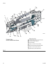
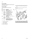
Reassembly
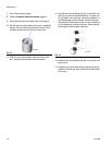
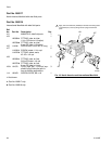
1. Non-circulating guns only: Lubricate the backup
o-ring (7†) and o-ring (6†) and install them on the
fluid outlet port plug (5). Install the plug in the fluid
outlet port of the fluid housing (2). See F
IG. 18.
2. All guns: Reinstall the gasket (4) in the fluid housing
(2).
3. Install the o-rings (22*, 23*) on the piston (20).
Install two o-rings (25*, 26*) on each of the piston
stems. Lubricate all the o-rings, the piston, and the
piston stems.
4. Align the gasket (15*) as shown in the exploded
view in Fig. 8.
If replacing gasket (15), place the gasket on the pis-
ton housing (1), then install the fluid housing (2).
Torque the two screws (18) to 30 in-lb (3.4 N•m)
5. Insert the piston (20) into the piston housing (1).
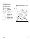
6. Remove the protective paper from the sticky side of
the gasket (16*) and adhere the gasket to the bot-
tom of the piston housing (1), making sure the three
holes in the gasket are properly aligned with the
matching holes in the housing.
7. Insert the needle assembly (14) into the front of the
fluid housing (2). Tighten to 50-60 in-lb (5.7-6.8
N•m).
8. Lubricate the threads of the diffuser-seat (10).
Screw it into the fluid housing (2) and torque to 65
in-lb (7.3 N•m).
9. Install the needle stop (21) on the needle. Coat the
setscrew (19) with semi-permanent anaerobic seal-
ant and install the screw into the needle stop.
Torque to 4-5 in-lb (0.45-0.56 N•m). Pull on the nee-
dle to make sure it seats fully.
10. Install the springs (28, 29).
11. Lubricate the threads of the piston housing (1).
Screw the cap (27) onto the housing until it bottoms
out.
12. Model 288053: Install the RAC housing (11) and
RAC spray tip (9) in the RAC air cap assembly (30).
Position the blue tip guard as desired and screw the
air cap assembly onto the gun until it bottoms out.
See Parts, page 25.
Assemble the standard tip and air cap.
13. Reinstall the gun on the manifold with the four
screws (17). Torque to 65 in-lb (7.3 N•m).
•See Accessories, page 34.
• Clean parts with a solvent that is compatible
with the parts and the fluid being sprayed.
When reinstalling the carbide seat, the tapered end
of the seat (red side) must point toward the gun tip.
The plastic seat, standard in Model 288044, can be
reinstalled in either direction. However, do not
reverse the direction of the seat if it is worn; it must
be replaced.
CAUTION
Be sure to keep the needle straight when installing it
in the piston housing. If the needle is bent it must be
replaced.